EP2918470A2 - System and method for controlling the display of service fields - Google Patents
System and method for controlling the display of service fields Download PDFInfo
- Publication number
- EP2918470A2 EP2918470A2 EP14184081.9A EP14184081A EP2918470A2 EP 2918470 A2 EP2918470 A2 EP 2918470A2 EP 14184081 A EP14184081 A EP 14184081A EP 2918470 A2 EP2918470 A2 EP 2918470A2
- Authority
- EP
- European Patent Office
- Prior art keywords
- service
- display
- threshold
- distance
- status
- Prior art date
- Legal status (The legal status is an assumption and is not a legal conclusion. Google has not performed a legal analysis and makes no representation as to the accuracy of the status listed.)
- Granted
Links
- 238000000034 method Methods 0.000 title claims abstract description 28
- 238000004422 calculation algorithm Methods 0.000 claims description 10
- 238000012545 processing Methods 0.000 claims description 8
- 238000012423 maintenance Methods 0.000 description 26
- 230000008569 process Effects 0.000 description 10
- 239000010705 motor oil Substances 0.000 description 9
- 230000008439 repair process Effects 0.000 description 6
- 238000010586 diagram Methods 0.000 description 5
- 239000002245 particle Substances 0.000 description 5
- 239000012530 fluid Substances 0.000 description 4
- 238000007689 inspection Methods 0.000 description 4
- 238000004364 calculation method Methods 0.000 description 2
- 230000008859 change Effects 0.000 description 2
- 238000004519 manufacturing process Methods 0.000 description 2
- 238000012986 modification Methods 0.000 description 2
- 230000004048 modification Effects 0.000 description 2
- 230000009471 action Effects 0.000 description 1
- 238000004590 computer program Methods 0.000 description 1
- 230000007547 defect Effects 0.000 description 1
- 230000006866 deterioration Effects 0.000 description 1
- 238000011160 research Methods 0.000 description 1
- 238000012546 transfer Methods 0.000 description 1
Images


Classifications
-
- B—PERFORMING OPERATIONS; TRANSPORTING
- B60—VEHICLES IN GENERAL
- B60W—CONJOINT CONTROL OF VEHICLE SUB-UNITS OF DIFFERENT TYPE OR DIFFERENT FUNCTION; CONTROL SYSTEMS SPECIALLY ADAPTED FOR HYBRID VEHICLES; ROAD VEHICLE DRIVE CONTROL SYSTEMS FOR PURPOSES NOT RELATED TO THE CONTROL OF A PARTICULAR SUB-UNIT
- B60W50/00—Details of control systems for road vehicle drive control not related to the control of a particular sub-unit, e.g. process diagnostic or vehicle driver interfaces
- B60W50/08—Interaction between the driver and the control system
- B60W50/14—Means for informing the driver, warning the driver or prompting a driver intervention
-
- B—PERFORMING OPERATIONS; TRANSPORTING
- B60—VEHICLES IN GENERAL
- B60K—ARRANGEMENT OR MOUNTING OF PROPULSION UNITS OR OF TRANSMISSIONS IN VEHICLES; ARRANGEMENT OR MOUNTING OF PLURAL DIVERSE PRIME-MOVERS IN VEHICLES; AUXILIARY DRIVES FOR VEHICLES; INSTRUMENTATION OR DASHBOARDS FOR VEHICLES; ARRANGEMENTS IN CONNECTION WITH COOLING, AIR INTAKE, GAS EXHAUST OR FUEL SUPPLY OF PROPULSION UNITS IN VEHICLES
- B60K35/00—Arrangement of adaptations of instruments
-
- B60K35/29—
-
- B—PERFORMING OPERATIONS; TRANSPORTING
- B60—VEHICLES IN GENERAL
- B60W—CONJOINT CONTROL OF VEHICLE SUB-UNITS OF DIFFERENT TYPE OR DIFFERENT FUNCTION; CONTROL SYSTEMS SPECIALLY ADAPTED FOR HYBRID VEHICLES; ROAD VEHICLE DRIVE CONTROL SYSTEMS FOR PURPOSES NOT RELATED TO THE CONTROL OF A PARTICULAR SUB-UNIT
- B60W50/00—Details of control systems for road vehicle drive control not related to the control of a particular sub-unit, e.g. process diagnostic or vehicle driver interfaces
- B60W50/0098—Details of control systems ensuring comfort, safety or stability not otherwise provided for
-
- B60K2360/186—
-
- B—PERFORMING OPERATIONS; TRANSPORTING
- B60—VEHICLES IN GENERAL
- B60W—CONJOINT CONTROL OF VEHICLE SUB-UNITS OF DIFFERENT TYPE OR DIFFERENT FUNCTION; CONTROL SYSTEMS SPECIALLY ADAPTED FOR HYBRID VEHICLES; ROAD VEHICLE DRIVE CONTROL SYSTEMS FOR PURPOSES NOT RELATED TO THE CONTROL OF A PARTICULAR SUB-UNIT
- B60W50/00—Details of control systems for road vehicle drive control not related to the control of a particular sub-unit, e.g. process diagnostic or vehicle driver interfaces
- B60W2050/0001—Details of the control system
- B60W2050/0002—Automatic control, details of type of controller or control system architecture
- B60W2050/0004—In digital systems, e.g. discrete-time systems involving sampling
- B60W2050/0006—Digital architecture hierarchy
-
- B—PERFORMING OPERATIONS; TRANSPORTING
- B60—VEHICLES IN GENERAL
- B60W—CONJOINT CONTROL OF VEHICLE SUB-UNITS OF DIFFERENT TYPE OR DIFFERENT FUNCTION; CONTROL SYSTEMS SPECIALLY ADAPTED FOR HYBRID VEHICLES; ROAD VEHICLE DRIVE CONTROL SYSTEMS FOR PURPOSES NOT RELATED TO THE CONTROL OF A PARTICULAR SUB-UNIT
- B60W2556/00—Input parameters relating to data
- B60W2556/45—External transmission of data to or from the vehicle
-
- G—PHYSICS
- G05—CONTROLLING; REGULATING
- G05B—CONTROL OR REGULATING SYSTEMS IN GENERAL; FUNCTIONAL ELEMENTS OF SUCH SYSTEMS; MONITORING OR TESTING ARRANGEMENTS FOR SUCH SYSTEMS OR ELEMENTS
- G05B23/00—Testing or monitoring of control systems or parts thereof
- G05B23/02—Electric testing or monitoring
- G05B23/0205—Electric testing or monitoring by means of a monitoring system capable of detecting and responding to faults
- G05B23/0259—Electric testing or monitoring by means of a monitoring system capable of detecting and responding to faults characterized by the response to fault detection
- G05B23/0283—Predictive maintenance, e.g. involving the monitoring of a system and, based on the monitoring results, taking decisions on the maintenance schedule of the monitored system; Estimating remaining useful life [RUL]
Definitions
- the present invention relates in general to the field of controlling the display of service fields, and in more particular, to a system and associated method for flexibly displaying service fields about status of service relevant components.
- CBS Condition Based Service
- BMW Corp. which monitors the condition of the vehicles in real time through numerous sensors and advanced algorithms. CBS can intelligently estimate current and future service requirements of the vehicles according to individual driver's driving habits and the distance travelled, the climate, the wear of the parts and the consumption of the engine oil etc. CBS thus provides the driver with tailored information about the scope of required maintenance work adapted to his/her personal driving standards, so that his/her vehicle will always be reliably operational.
- the distance to be driven or the time to the next maintenance may be displayed briefly in the vehicle's instrument cluster after switching on the ignition.
- the driver can have the service fields and respective events, such as residual distances and residual times for selected maintenance tasks including any legally prescribed dates displayed on the Central Information Display (CID), also known as Head Unit or Control Display, as shown in Figs.1A-1C .
- CID Central Information Display
- Figs.1A-1C Within the service fields, symbols can be shown which indicate the service/maintenance status. In Fig. 1A , everything is ok and the symbols can be shown as green circular surfaces containing the word "OK", i.e. indicating that currently no service is required. In Fig. 1B , circular surface in service field "brake pad front" changes from green to yellow and contains a warning triangle, i.e.
- brake pad front will need some service within a given time or distance.
- circular surface for "brake pad front” changes from yellow to red, it needs some service as soon as possible.
- the displayed service requirements are not limited to above events. Some events could be left and other events can be included, such as for battery, particle filter etc.
- the present CBS system has a fixed scheme of displayed fields for service related events (e.g. brake pad front, brake pad rear, engine oil etc.), in which every event, such as the engine oil will be shown from 100% to 0% ( 30000 km to 0 or - xy km ). At a specific level (e.g., "yellow”) the car will send a teleservice call (via head unit) and inform the dealer.
- service related events e.g. brake pad front, brake pad rear, engine oil etc.
- the present invention provides an advanced Condition Based Service system-the Condition Based Repair system- to address the shortage of the current CBS.
- An aspect of the present invention is to have a well-arranged display of service information which enables the driver to easily recognize the status of the vehicle.
- the present invention only the service field about the status of service-relevant component which is relevant within short to medium time frame is displayed, that is, when the status of the service-relevant component is up to standard, the corresponding service field will not be displayed, and the corresponding service field is only displayed when the status of the service-relevant component is not up to standard.
- a system for controlling the display of at least one service field about the status of at least one service-relevant component of a vehicle comprising: a display configured to display said service field; a master connected to said display; an electronic control unit (ECU) comprising a client; and at least one sensor connected to said client and configured to sense the status of said component, wherein said master is configured to control the display to display said service field about said status only when said status is not up to a standard.
- ECU electronice control unit
- the status is the service requirements of the components of the vehicle.
- system further comprises an instrument cluster for displaying the distance to be driven or time to the next service for a specific period after switching on the ignition.
- system further comprises a total distance recorder configured to record the total distance travelled through a total distance counter.
- the client includes: an inputting unit configured to read in the following data for each service relevant component: sensor data from the plurality of sensors; distance data from the total distance recorder; and time data from a clock which may be integrated in the vehicle; a parameter database containing parameters for each service relevant component; a plurality of algorithms units configured to calculate remaining distances and characteristic values for each service relevant component; and an outputting unit configured to forward the calculated remaining distances and characteristic values for each service relevant component to said master.
- the master includes: a threshold database containing threshold values for each service relevant component; a plurality of comparators configured to: compare the calculated remaining distance with corresponding threshold distance stored in the threshold database; compare the time data with corresponding threshold time stored in the threshold database; compare the calculated characteristic value with the corresponding threshold value stored in the threshold database; and a control unit configured to control the display to display the respective service field only when at least one of the following is met: the time data is equal to or later than the threshold time, the calculated remaining distance is equal to or less than the threshold distance and the calculated characteristic value is equal to or less than the threshold characteristic value.
- the client includes: an inputting unit configured to read in the following data for each service relevant component: sensor data from the plurality of sensors; distance data from the total distance recorder; and time data from a clock which may be integrated in the vehicle; a parameter database containing parameters for each service relevant component; a plurality of algorithms units configured to calculate remaining distances and characteristic values for each service relevant component; a threshold database containing threshold values for each service relevant component; and a plurality of comparators configured to: compare the calculated remaining distance with corresponding threshold distance stored in the threshold database; compare the time data with corresponding threshold time stored in the threshold database; compare the calculated characteristic value with corresponding threshold value stored in the threshold database.
- the master includes: a control unit configured to control the display to display the respective service field only when at least one of the following is meet: the time data is equal to or later than the threshold time, the calculated remaining distance is equal to or less than the threshold distance and the calculated characteristic value is equal to or less than the threshold characteristic value.
- the system further comprises: a teleservice module connected to the instrument cluster, configured to connect the vehicle to a service centre of a service dealer and transmits data of the vehicle's service requirements in advance to the service centre when the status of the service relevant component turns to not up to standard.
- the teleservice module and/or the service centre may comprise electronic components, in particular wired and/or wireless data interfaces, computer components and/or respective computer program modules to control data transfer and/or to process data.
- information on service requirements is continually saved in a remote control.
- a method for controlling the display of at least one service field about the status of at least one service-relevant component on a display of a vehicle comprising: receiving data relating to said status; processing said data; and displaying said service field about the status on said display only when said status is not up to standard.
- the status is the service requirements of the components of the vehicle.
- the method further comprises: displaying the distance to be driven or time to the next service for a specific period on an instrument cluster after switching on the ignition.
- the method further comprises: recording the total distance travelled through a total distance counter.
- receiving data relating to said status comprises: reading in the following data for each service relevant component: sensor data from the plurality of sensors; distance data from the total distance recorder; and time data from a clock.
- the clock is integrated in the car, in particular within an ECU or within an instrument display.
- processing said data comprises: calculating remaining distances and characteristic values for each service relevant component; comparing the calculated remaining distance with corresponding threshold distance stored in a threshold database; comparing the time data with corresponding threshold time stored in the threshold database; compare the calculated characteristic value with corresponding threshold value stored in the threshold database.
- displaying said service field about the status on said display only when said status is not up to standard comprises: controlling the display to display the respective service field only when at least one of the following is meet: the time data is equal to or later than the threshold time, the calculated remaining distance is equal to or less than the threshold distance and the calculated characteristic value is equal to or less than the threshold characteristic value.
- processing said data is performed by a client.
- the step of controlling the display to display the service field is performed by a master.
- the present invention provides a Condition Based Repair (CBR) system for flexibly displaying service fields about the status of service relevant components of a vehicle.
- CBR Condition Based Repair
- the system enables the driver to easily recognize the status of the vehicle.
- service should be interpreted broadly. It comprises but is not limited to the term “maintenance”.
- the information about the status will not be displayed, and the information is only displayed when the status of the service relevant components is not up to standard.
- the information about the status of the service relevant components e.g., the engine oil
- the status of the service relevant components is up to standard (e.g., denoted as "green").
- the information about the status of the service relevant components will only be displayed when the status becomes not up to standard, e.g., when the level becomes "yellow” and the teleservice call will be send.
- Such CBR system will be described with reference to Figs. 2A-2C .
- Fig. 2A when everything is ok, only service fields for brake fluid, statutory goods vehicle inspection, handover inspection and engine oil service are displayed (e.g., in green circular surfaces). No information is displayed for service fields such as brake pads front/rear since they are such good/less worn off (e.g. within a new car) that service/maintenance is not required for a long time, as shown by the empty rectangle.
- service fields such as brake pads front/rear since they are such good/less worn off (e.g. within a new car) that service/maintenance is not required for a long time, as shown by the empty rectangle.
- service field "brake pad front" shows up in the control display (e.g., in yellow circular surface), it indicates that it will need some service within a given time or distance. Still, no information is displayed for other parts such as the brake pad rear since they are such good/less worn off (e.g. have been maintained not long ago) that service/maintenance is not required for a long time.
- the display of the service field for "brake pad front" will be upgraded, such as changes from yellow to red in circular surface, it indicates that it needs some service as soon as possible, as shown in Fig. 2C , so as to maintain the road and operational safety of the vehicle. Still, no information is displayed for other parts such as the brake pad rear since they are such good/less worn off (e.g. have been maintained not long ago) that service is not required for a long time..
- the service advisor of the service centre can read out this data from the remote control and suggest a set of routine maintenances optimized on this basis.
- FIG. 3 An example block diagram of the CBR system 300 according to an embodiment of the present invention is shown in Fig. 3 , the system includes a Central Information Display (CID) 301 for displaying information about the status of service relevant components; a CBR master 302 which is connected to the CID 301; an electronic control unit (ECU) 303 comprising CBR Client 304; and a plurality of sensors 305 connected to the CBR Client 304 and used for sensing the condition of the vehicle, such as the temperature of the motor, the amount of the engine oil, the wear of the brake pad front etc.
- CID Central Information Display
- ECU electronice control unit
- sensors 305 connected to the CBR Client 304 and used for sensing the condition of the vehicle, such as the temperature of the motor, the amount of the engine oil, the wear of the brake pad front etc.
- the system 300 also includes an instrument cluster KOMBI (not shown in Fig. 3 ), the distance to be driven or time to the next maintenance for the service relevant components which are relevant within short to medium time frame can be displayed briefly in the KOMBI after switching on the ignition to remind the driver.
- the KOMBI is connected to a teleservice module, which connects the vehicle (e.g. by mobile phone connection) to service dealer and transmits data of the vehicle's corresponding service requirements (e.g. "brake pads front") in advance to service centre when the status of the service relevant components becomes not up to standard. But the data of the service requirements not necessarily need to be automatically forwarded to the service centre at the time when the status of the service relevant components becomes not up to standard.
- a calculation of the respective characteristic value of the respective vehicle components could be carried out by respective component-specific algorithms and parameters stored within the clients.
- the CBR client 304 includes an inputting unit 401 used for reading in data for each service relevant component, such as reading in sensor data from the plurality of sensors 305, reading in distance data from the total distance recorder, and reading in time data from a system clock of the KOMBI. Please note that the time data can also be read in from any other clock which could be provided within the vehicle ECUs.
- a parameter database 402 is used for storing parameters/values such as the distance to be driven for every maintenance etc., which are typically factory set and remain unchanged during lifetime of the vehicle. The parameters/values may be provided by the vehicle manufacturer. However they might be provided by manufacturers of respective vehicle components as well, e.g. by a manufacturer of a brake system.
- Algorithms units 403 are used for calculating a remaining distance and characteristic values for each service relevant component.
- An outputting unit 404 is used for forwarding the calculated values for each service relevant component to the CBR master 302, as shown in Fig. 4 .
- the master 302 includes a threshold database 501 containing values, e.g. threshold values, or characteristic curves for respective component; a plurality of comparators 502 in which the value of remaining distance input from the client 304 is compared with a given threshold value for the remaining distance stored in the database 501.
- the time read in is compared with the corresponding threshold time to the next maintenance stored in the database 501 and the calculated characteristic value for each service relevant component is compared with the corresponding threshold value stored in the threshold database.
- a control unit is used for controlling the display of the respective service field based on the comparison result.
- the threshold values and characteristic curves are factory set and remain unchanged during lifetime of the vehicle. However, in principle, they could be changed/modified later, e.g. by a maintenance service dealer.
- the CBR client 304 includes an inputting unit 401 used for reading in data for each service relevant component, such as reading in sensor data from the plurality of sensors 305, reading in distance data from the total distance recorder, and reading in time data from the clock of the KOMBI.
- a parameter database 402 is used for storing parameters such as the distance to be driven for every maintenance etc.
- Algorithms units 403 is used for calculating a remaining distance and characteristic values for each service relevant component.
- a threshold database 405 contains values, e.g.
- At least one comparator 406 is provided, in which the value of remaining distance is compared with a given threshold value for the remaining distance stored in the database 405.
- the time read in is compared with the corresponding threshold time to the next maintenance stored in the database 405 and the calculated characteristic value for each service relevant component is compared with the corresponding threshold value stored in the threshold database 405.
- the CBR master controls the display of the respective service field according to the comparison results. Accordingly, only those service fields are displayed for which a respective status is not up to a predetermined standard, in particular if at least one respective measured value and/or calculated characteristic value is over or below a respective threshold value. For example, if a calculated remaining distance of e.g.
- the driver may also recognize that he/she should observe the service field for any changes within the near future.
- the circular surface in service field "brake pad front" may be displayed in yellow or change from green to yellow, respectively, and may contain a warning triangle as shown in Fig. 2B .
- the circular surface may change from yellow to red if the calculated remaining distance is less than a further threshold value of e.g. 1000 km as shown in Fig. 2C .
- the respective characteristic values could be already (pre)calculated by a sensor unit included in the ECU 303 outside of the client 304 which sends such pre-calculated value of the service relevant component to the client.
- the system 300 also includes On Board Diagnostics (OBD) and a total distance recorder (not shown in Fig.3 ), wherein the OBD is a standardized interface to car diagnostic equipment of service dealer software, the total distance recorder can be used for recording the total distance the vehicle has travelled in real time through a total distance counter.
- OBD On Board Diagnostics
- a total distance recorder not shown in Fig.3
- the CBR master 302 can be integrated in an electronic control unit (ECU) of the vehicle, e.g. in control unit of the instrument cluster KOMBI or in a central control unit of the vehicle.
- ECU electronice control unit
- Fig. 7 shows an example flow chart illustrating the process for controlling the display of the service requirements according to an embodiment of the present invention.
- the flow chart 700 starts when switching on the ignition.
- data relating to status of at least one service-relevant component is received.
- said data is processed.
- at least one item of information about a status is controlled to be displayed only when said status is not up to a predetermined standard.
- step 701 can further includes steps 710-730, at step 710, the inputting unit 401 reads in distance data from the total distance recorder, at step 720, the inputting unit 401 reads in time data from the clock of the KOMBI instrument. Please note that the time data can also be read in from any other clock which could be provided within the vehicle ECUs.
- the inputting unit 401 reads in sensor data from the plurality of sensors 305, such as the climate, the wear of each service related component etc..
- Step 702 further includes steps 740-770.
- the algorithm unit 403 calculates characteristic value for each service relevant component from respective sensor data, and calculates the residual distance for each service relevant component from the distance data read in.
- the residual distance can be calculated by the corresponding sample characteristic value (i.e., the prescribed total distance) to the next maintenance for each service relevant component stored in the parameter database 402 minus the total distance travelled, which can be expressed by the total distance read in.
- the comparator (406, 502) compares the time read in with the corresponding threshold time to the next maintenance stored in the database (405, 501). If the time read in is equal to or later than the threshold time, then the process proceeds to step 703, otherwise the process proceeds to step 760.
- the comparator (406, 502) compares the residual distance for each service relevant component with the corresponding threshold distance to be driven to the next maintenance stored in the database (405, 501), if the residual distance is equal to or less than the threshold distance, then the process proceeds to step 703, otherwise the process proceeds to step 770.
- the comparator (406, 502) compares the calculated characteristic value for each service relevant component with the corresponding threshold value stored in the threshold database (405, 501), if the calculated characteristic value is equal to or less than the threshold characteristic value, then the process proceeds to step 703, otherwise the process ends, no information will be displayed for the relevant service field.
- the order of steps 710-730 is changeable. That is to say, the above mentioned time data, distance data and the sensor data can be read-in in any order.
- the order of steps 750-770 is also changeable. That is to say, so long as one of the three comparing results is a positive result, the process proceeds to step 703, otherwise the process ends, regardless of the order of the three comparisons.
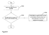
- steps 750-770 it is not necessary for every service relevant component to check for all three values (time, distance, characteristic value) according to steps 750-770 as shown in Fig. 8 . Rather, for some components such as the particle filter, it could be sufficient to check only for one or two of the values, e.g. only for time. In this case, steps 710, 730, 740 and 760-770 can be omitted, as shown in Fig. 9 .
- a value such as the time is within the meaning of a "characteristic value”.
- the characteristic value can also be calculated based on both time and residual distance values, whether alone, in combination and/or in combination with further values derived from the plurality of sensors.
- steps 750-760 can be omitted, as shown in Fig. 10 . It will be understood that the steps for controlling the display of the status of each service relevant component can vary among the components.
- the algorithm unit 403 calculates characteristic value for each service relevant component from respective sensor data.
- the sensor data can be the wear condition of the brake pad, in particular, the thickness of the brake pad, thus the characteristic value of the brake pad can be calculated by the corresponding sample characteristic value (i.e., the factory set thickness) of the brake pad minus the thickness read in.
- the characteristic value of other service relevant component can also be calculated by the corresponding sample characteristic value(s) minus the corresponding data read in. While in the foregoing the term "brake pad" was used in singular form, it is clear that several brake pads can be checked and evaluated jointly.
- all brake pads of a respective axle front/rear and/or all brake pads belonging to a specific wheel can be jointly evaluated as a group.
- the respective service field can be displayed if at least one of the respective brake pads of the group has a thickness below the respective threshold/sample characteristic value.
- Table 1 shows some sample characteristic values.
- the characteristic values correspond to or serve as a basis for calculating at least one "residual value" such as a residual thickness, a residual distance or a residual time etc. until the next service/maintenance action for the respective component is required.
- Table 1 Sample Characteristic Values Component Sample Characteristic Value(s) Brake Thickness of Brake Disc (measured by Brake Sensor), Total Distance (e.g. 60.000 km) Brake Fluid Age, Total Distance Engine Oil Deterioration Value(s) calculated by Motor ECU based on Data of Motor Sensors Battery Age, Battery characteristic electric values measured by resp. sensors Particle Filter Total Distance (e.g. 160.000 km), Engine Use Data, e.g. numbers of short distance drives and long distance drives, Particle Filter Sensor Data
- the invention allows a service field to be displayed only if the status of the service relevant component is not up to standard, that is only if the service relevant component is going to be service relevant within a given time or distance.
- the information about the status of the service relevant component can be displayed flexibly, such that the critical status of the service relevant component can be recognized from the vehicles and displayed to the driver, and further be sent to the service dealer via the teleservice call (remote service).
- the dealer can provide the owner of the vehicle with suggestion in advance and order replacement parts timely.
- the relationship between the dealer and the owner of the vehicle can be further improved through the invented CBR system. Further, the profit margin is increased due to the additional sale of the replacement parts.
Abstract
Description
- The present invention relates in general to the field of controlling the display of service fields, and in more particular, to a system and associated method for flexibly displaying service fields about status of service relevant components.
- The increasing popularity of motor vehicles facilitates various researches about the motor vehicles, including maintenance of the motor vehicles. Each driver has his/her own driving habits, determining the time and contents of the required maintenance. Just carrying out according to the average distance given by the Owner's Handbook for Vehicle is often too early (e.g., if the driver is usually driving very cautious and slowly) thus wasting time and money, or too late (e.g., if the driver is usually driving sportive) thus influencing the condition of the vehicle, which may even endanger the vehicle occupants and other road users.
- To overcome the above defects, Condition Based Service (CBS) was introduced in the market. CBS is an on-board monitor system proposed by BMW Corp., which monitors the condition of the vehicles in real time through numerous sensors and advanced algorithms. CBS can intelligently estimate current and future service requirements of the vehicles according to individual driver's driving habits and the distance travelled, the climate, the wear of the parts and the consumption of the engine oil etc. CBS thus provides the driver with tailored information about the scope of required maintenance work adapted to his/her personal driving standards, so that his/her vehicle will always be reliably operational.
- Information on maintenance requirements is continually saved by CBS. By means of a remote control, the service advisor of a service dealer can read out this data from the remote control and suggest a set of routine maintenances optimized on this basis.
- The distance to be driven or the time to the next maintenance may be displayed briefly in the vehicle's instrument cluster after switching on the ignition. The driver can have the service fields and respective events, such as residual distances and residual times for selected maintenance tasks including any legally prescribed dates displayed on the Central Information Display (CID), also known as Head Unit or Control Display, as shown in
Figs.1A-1C . Within the service fields, symbols can be shown which indicate the service/maintenance status. InFig. 1A , everything is ok and the symbols can be shown as green circular surfaces containing the word "OK", i.e. indicating that currently no service is required. InFig. 1B , circular surface in service field "brake pad front" changes from green to yellow and contains a warning triangle, i.e. brake pad front will need some service within a given time or distance. InFig. 1C , circular surface for "brake pad front" changes from yellow to red, it needs some service as soon as possible. It should be noted that, although only brake pad front, brake pad rear, brake fluid, statutory goods vehicle inspection, handover inspection and engine oil service are shown inFigs. 1A-1C , it will be appreciated that the displayed service requirements are not limited to above events. Some events could be left and other events can be included, such as for battery, particle filter etc. - The present CBS system has a fixed scheme of displayed fields for service related events (e.g. brake pad front, brake pad rear, engine oil etc.), in which every event, such as the engine oil will be shown from 100% to 0% ( 30000 km to 0 or - xy km ). At a specific level (e.g., "yellow") the car will send a teleservice call (via head unit) and inform the dealer. However, it is not flexible with regard to the scheme of displayed fields.
- Thus there is a need for the flexibility of the service information presented to a driver.
- The present invention provides an advanced Condition Based Service system-the Condition Based Repair system- to address the shortage of the current CBS. An aspect of the present invention is to have a well-arranged display of service information which enables the driver to easily recognize the status of the vehicle.
- According to the present invention, only the service field about the status of service-relevant component which is relevant within short to medium time frame is displayed, that is, when the status of the service-relevant component is up to standard, the corresponding service field will not be displayed, and the corresponding service field is only displayed when the status of the service-relevant component is not up to standard.
- In accordance with an exemplary embodiment of the present invention, a system for controlling the display of at least one service field about the status of at least one service-relevant component of a vehicle is provided, comprising: a display configured to display said service field; a master connected to said display; an electronic control unit (ECU) comprising a client; and at least one sensor connected to said client and configured to sense the status of said component, wherein said master is configured to control the display to display said service field about said status only when said status is not up to a standard.
- In an example of the present invention, the status is the service requirements of the components of the vehicle.
- In another example of the present invention, the system further comprises an instrument cluster for displaying the distance to be driven or time to the next service for a specific period after switching on the ignition.
- In another example of the present invention, the system further comprises a total distance recorder configured to record the total distance travelled through a total distance counter.
- In another example of the present invention, the client includes: an inputting unit configured to read in the following data for each service relevant component: sensor data from the plurality of sensors; distance data from the total distance recorder; and time data from a clock which may be integrated in the vehicle; a parameter database containing parameters for each service relevant component; a plurality of algorithms units configured to calculate remaining distances and characteristic values for each service relevant component; and an outputting unit configured to forward the calculated remaining distances and characteristic values for each service relevant component to said master.
- In another example of the present invention, the master includes: a threshold database containing threshold values for each service relevant component; a plurality of comparators configured to: compare the calculated remaining distance with corresponding threshold distance stored in the threshold database; compare the time data with corresponding threshold time stored in the threshold database; compare the calculated characteristic value with the corresponding threshold value stored in the threshold database; and a control unit configured to control the display to display the respective service field only when at least one of the following is met: the time data is equal to or later than the threshold time, the calculated remaining distance is equal to or less than the threshold distance and the calculated characteristic value is equal to or less than the threshold characteristic value.
- In another example of the present invention, the client includes: an inputting unit configured to read in the following data for each service relevant component: sensor data from the plurality of sensors; distance data from the total distance recorder; and time data from a clock which may be integrated in the vehicle; a parameter database containing parameters for each service relevant component; a plurality of algorithms units configured to calculate remaining distances and characteristic values for each service relevant component; a threshold database containing threshold values for each service relevant component; and a plurality of comparators configured to: compare the calculated remaining distance with corresponding threshold distance stored in the threshold database; compare the time data with corresponding threshold time stored in the threshold database; compare the calculated characteristic value with corresponding threshold value stored in the threshold database.
- In another example of the present invention, the master includes: a control unit configured to control the display to display the respective service field only when at least one of the following is meet: the time data is equal to or later than the threshold time, the calculated remaining distance is equal to or less than the threshold distance and the calculated characteristic value is equal to or less than the threshold characteristic value.
- In another example of the present invention, the system further comprises: a teleservice module connected to the instrument cluster, configured to connect the vehicle to a service centre of a service dealer and transmits data of the vehicle's service requirements in advance to the service centre when the status of the service relevant component turns to not up to standard. The teleservice module and/or the service centre may comprise electronic components, in particular wired and/or wireless data interfaces, computer components and/or respective computer program modules to control data transfer and/or to process data.
- In another example of the present invention, information on service requirements is continually saved in a remote control.
- In accordance with another exemplary embodiment of the present invention, a method for controlling the display of at least one service field about the status of at least one service-relevant component on a display of a vehicle is provided, comprising: receiving data relating to said status; processing said data; and displaying said service field about the status on said display only when said status is not up to standard.
- In an example of the present invention, the status is the service requirements of the components of the vehicle.
- In another example of the present invention, the method further comprises: displaying the distance to be driven or time to the next service for a specific period on an instrument cluster after switching on the ignition.
- In another example of the present invention, the method further comprises: recording the total distance travelled through a total distance counter.
- In another example of the present invention, receiving data relating to said status comprises: reading in the following data for each service relevant component: sensor data from the plurality of sensors; distance data from the total distance recorder; and time data from a clock. In an advantageous embodiment the clock is integrated in the car, in particular within an ECU or within an instrument display.
- In another example of the present invention, processing said data comprises: calculating remaining distances and characteristic values for each service relevant component; comparing the calculated remaining distance with corresponding threshold distance stored in a threshold database; comparing the time data with corresponding threshold time stored in the threshold database; compare the calculated characteristic value with corresponding threshold value stored in the threshold database.
- In another example of the present invention, displaying said service field about the status on said display only when said status is not up to standard comprises: controlling the display to display the respective service field only when at least one of the following is meet: the time data is equal to or later than the threshold time, the calculated remaining distance is equal to or less than the threshold distance and the calculated characteristic value is equal to or less than the threshold characteristic value.
- In another example of the present invention, processing said data is performed by a client.
- In another example of the present invention, the step of controlling the display to display the service field is performed by a master.
- In another example of the present invention, wherein both steps of processing said data and controlling the display to display the service field are performed by a master.
- Further scope of applicability of the present invention will become apparent from the detailed description given hereinafter. However, it should be understood that the detailed description and specific examples, while indicating preferred embodiments of the invention, are given by way of illustration only, since various changes and modifications within the spirit and scope of the invention will become apparent to those skilled in the art from the following detailed description.
- The above and other aspects and advantages of the present invention will become apparent from the following detailed description of exemplary embodiments taken in conjunction with the accompanying drawings which illustrate, by way of example, the principles of the invention.
-
Figs. 1A-1C illustrates display of service requirements in service fields within Head-Unit / CID according to state of the art, BMW Condition Based Service CBS 5; -
Figs. 2A-2C illustrates the display of service requirements in service fields within Head-Unit / CID according to an exemplary embodiment of the present invention; -
Fig. 3 illustrates a block diagram of the Condition Based Repair system in accordance with an exemplary embodiment of the present invention; -
Fig. 4 illustrates a block diagram of a client in the Condition Based Repair system in accordance with an exemplary embodiment of the present invention; -
Fig. 5 illustrates a block diagram of a master in the Condition Based Repair system in accordance with an exemplary embodiment of the present invention; -
Fig. 6 illustrates a block diagram of a client in the Condition Based Repair system in accordance with another exemplary embodiment of the present invention; -
Fig. 7 illustrates a flow chart showing the controlling of the display of the service field about the status of service relevant components in accordance with an exemplary embodiment of the present invention. -
Fig. 8 illustrates a flow chart showing the controlling of the display of the service field about the status of service relevant components in accordance with another exemplary embodiment of the present invention. -
Fig. 9 illustrates a flow chart showing the controlling of the display of the service field about the status of service relevant components in accordance with yet another exemplary embodiment of the present invention. -
Fig. 10 illustrates a flow chart showing the controlling of the display of the service field about the status of service relevant components in accordance with still another exemplary embodiment of the present invention. - In the following detailed description, numerous specific details are set forth to provide a thorough understanding of the described exemplary embodiments. It will be apparent, however, to one skilled in the art that the described embodiments can be practiced without some or all of these specific details. In other exemplary embodiments, well known structures or process steps have not been described in detail in order to avoid unnecessarily obscuring the concept of the present invention.
- The present invention provides a Condition Based Repair (CBR) system for flexibly displaying service fields about the status of service relevant components of a vehicle. The system enables the driver to easily recognize the status of the vehicle. For the present description, the term "service" should be interpreted broadly. It comprises but is not limited to the term "maintenance".
- In accordance with an exemplary embodiment of the present invention, in the present invented CBR system, when the status of the service relevant components is up to standard, the information about the status will not be displayed, and the information is only displayed when the status of the service relevant components is not up to standard. Thus there is an additional possibility for specific parts, the information about the status of the service relevant components (e.g., the engine oil) will not be shown from 100%, i.e., when the status of the service relevant components is up to standard (e.g., denoted as "green"). The information about the status of the service relevant components will only be displayed when the status becomes not up to standard, e.g., when the level becomes "yellow" and the teleservice call will be send. Such CBR system will be described with reference to
Figs. 2A-2C . - According to the principle of CBR, only the information about the status of the service-relevant components which are relevant within short to medium time frame is displayed. Accordingly, by providing threshold values individually for each component, the display of the service field is controlled component-wise. E.g., for displaying the service field for "brake fluid", a distance threshold value of 80.000 km could be provided, whereas for displaying the service field for a "particle filter", a distance threshold value of 120.000 km could be provided. Nevertheless it is noted that service fields and corresponding service-relevant status information for certain additional components (e.g. for engine oil or brake pads) are always displayed, independently of the respective component's wear out status.
- Referring to
Fig. 2A , when everything is ok, only service fields for brake fluid, statutory goods vehicle inspection, handover inspection and engine oil service are displayed (e.g., in green circular surfaces). No information is displayed for service fields such as brake pads front/rear since they are such good/less worn off (e.g. within a new car) that service/maintenance is not required for a long time, as shown by the empty rectangle. - When the vehicles have been used for a given time or travelled for a certain distance, some of the parts, such as the brake pad front may need some maintenance. Referring to
Fig. 2B , service field "brake pad front" shows up in the control display (e.g., in yellow circular surface), it indicates that it will need some service within a given time or distance. Still, no information is displayed for other parts such as the brake pad rear since they are such good/less worn off (e.g. have been maintained not long ago) that service/maintenance is not required for a long time. - If the driver ignored the maintenance requirements, after a certain time period or distance, the display of the service field for "brake pad front" will be upgraded, such as changes from yellow to red in circular surface, it indicates that it needs some service as soon as possible, as shown in
Fig. 2C , so as to maintain the road and operational safety of the vehicle. Still, no information is displayed for other parts such as the brake pad rear since they are such good/less worn off (e.g. have been maintained not long ago) that service is not required for a long time.. - Information on maintenance requirements is continually saved in the remote control, the service advisor of the service centre can read out this data from the remote control and suggest a set of routine maintenances optimized on this basis.
- An example block diagram of the
CBR system 300 according to an embodiment of the present invention is shown inFig. 3 , the system includes a Central Information Display (CID) 301 for displaying information about the status of service relevant components; aCBR master 302 which is connected to theCID 301; an electronic control unit (ECU) 303 comprisingCBR Client 304; and a plurality ofsensors 305 connected to theCBR Client 304 and used for sensing the condition of the vehicle, such as the temperature of the motor, the amount of the engine oil, the wear of the brake pad front etc.. - In another embodiment, the
system 300 also includes an instrument cluster KOMBI (not shown inFig. 3 ), the distance to be driven or time to the next maintenance for the service relevant components which are relevant within short to medium time frame can be displayed briefly in the KOMBI after switching on the ignition to remind the driver. In an embodiment, the KOMBI is connected to a teleservice module, which connects the vehicle (e.g. by mobile phone connection) to service dealer and transmits data of the vehicle's corresponding service requirements (e.g. "brake pads front") in advance to service centre when the status of the service relevant components becomes not up to standard. But the data of the service requirements not necessarily need to be automatically forwarded to the service centre at the time when the status of the service relevant components becomes not up to standard. There may be still some delay in terms of time and/or remaining driving distance before the data are transmitted, but the transmittal should be before the status being upgraded, such as changes from yellow to red in circular surface as shown inFig. 2C which indicates that it needs some service as soon as possible. - According to embodiments of the present invention, a calculation of the respective characteristic value of the respective vehicle components (motor, carriage) could be carried out by respective component-specific algorithms and parameters stored within the clients.
- According to an embodiment, the
CBR client 304 includes aninputting unit 401 used for reading in data for each service relevant component, such as reading in sensor data from the plurality ofsensors 305, reading in distance data from the total distance recorder, and reading in time data from a system clock of the KOMBI. Please note that the time data can also be read in from any other clock which could be provided within the vehicle ECUs. Aparameter database 402 is used for storing parameters/values such as the distance to be driven for every maintenance etc., which are typically factory set and remain unchanged during lifetime of the vehicle. The parameters/values may be provided by the vehicle manufacturer. However they might be provided by manufacturers of respective vehicle components as well, e.g. by a manufacturer of a brake system.Algorithms units 403 are used for calculating a remaining distance and characteristic values for each service relevant component. Anoutputting unit 404 is used for forwarding the calculated values for each service relevant component to theCBR master 302, as shown inFig. 4 . - According to an embodiment, as shown in
Fig. 5 , themaster 302 includes athreshold database 501 containing values, e.g. threshold values, or characteristic curves for respective component; a plurality ofcomparators 502 in which the value of remaining distance input from theclient 304 is compared with a given threshold value for the remaining distance stored in thedatabase 501. In addition, the time read in is compared with the corresponding threshold time to the next maintenance stored in thedatabase 501 and the calculated characteristic value for each service relevant component is compared with the corresponding threshold value stored in the threshold database. Furthermore, a control unit is used for controlling the display of the respective service field based on the comparison result. Typically the threshold values and characteristic curves are factory set and remain unchanged during lifetime of the vehicle. However, in principle, they could be changed/modified later, e.g. by a maintenance service dealer. - According to another embodiment, all calculations and comparisons are carried out within the respective CBR client and the CBR client only sends a simple signal to the CBR master indicating whether the respective service field shall be displayed or not. In this case, as shown in
Fig. 6 , theCBR client 304 includes aninputting unit 401 used for reading in data for each service relevant component, such as reading in sensor data from the plurality ofsensors 305, reading in distance data from the total distance recorder, and reading in time data from the clock of the KOMBI.A parameter database 402 is used for storing parameters such as the distance to be driven for every maintenance etc.Algorithms units 403 is used for calculating a remaining distance and characteristic values for each service relevant component. Athreshold database 405 contains values, e.g. threshold values or values of characteristic curves for a respective component. At least onecomparator 406 is provided, in which the value of remaining distance is compared with a given threshold value for the remaining distance stored in thedatabase 405. In addition, the time read in is compared with the corresponding threshold time to the next maintenance stored in thedatabase 405 and the calculated characteristic value for each service relevant component is compared with the corresponding threshold value stored in thethreshold database 405. The CBR master controls the display of the respective service field according to the comparison results. Accordingly, only those service fields are displayed for which a respective status is not up to a predetermined standard, in particular if at least one respective measured value and/or calculated characteristic value is over or below a respective threshold value. For example, if a calculated remaining distance of e.g. 4000 km for "brake pad front" is below a threshold value of e.g. 5000 km, the respective service field "brake pad front" is displayed, controlled by CBR master as shown inFig. 2A . At the same time, a respective symbol indicating the respective service status could be displayed (not shown inFig. 2A ). Accordingly, "brake pad front" can still be considered in status up to standard, i.e. being OK. The symbol for "brake pad front" could thus be shown as a green circular surface containing the word "OK" (not shown inFig. 2A ). Nevertheless, due to display of the service field as such as shown inFig. 2A , the driver may recognize that the time for maintenance of brake pads is coming closer. Due to this display, the driver may also recognize that he/she should observe the service field for any changes within the near future. Instead of first indicating the green symbol or later on (e.g., if the calculated remaining distance is less than a second threshold value of e.g. 3000 km) the circular surface in service field "brake pad front" may be displayed in yellow or change from green to yellow, respectively, and may contain a warning triangle as shown inFig. 2B . The circular surface may change from yellow to red if the calculated remaining distance is less than a further threshold value of e.g. 1000 km as shown inFig. 2C . - Alternatively, the respective characteristic values could be already (pre)calculated by a sensor unit included in the
ECU 303 outside of theclient 304 which sends such pre-calculated value of the service relevant component to the client. - In an embodiment, the
system 300 also includes On Board Diagnostics (OBD) and a total distance recorder (not shown inFig.3 ), wherein the OBD is a standardized interface to car diagnostic equipment of service dealer software, the total distance recorder can be used for recording the total distance the vehicle has travelled in real time through a total distance counter. - In another embodiment, the
CBR master 302 can be integrated in an electronic control unit (ECU) of the vehicle, e.g. in control unit of the instrument cluster KOMBI or in a central control unit of the vehicle. -
Fig. 7 shows an example flow chart illustrating the process for controlling the display of the service requirements according to an embodiment of the present invention. The flow chart 700 starts when switching on the ignition. At step 701, data relating to status of at least one service-relevant component is received. At step 702, said data is processed. Atstep 703, at least one item of information about a status is controlled to be displayed only when said status is not up to a predetermined standard. - According to embodiments of the present invention, the flow chart 700 can be carried out by the
client 304 and themaster 302 together. According to another embodiment, as shown inFig. 8 , step 701 can further includes steps 710-730, atstep 710, the inputtingunit 401 reads in distance data from the total distance recorder, atstep 720, the inputtingunit 401 reads in time data from the clock of the KOMBI instrument. Please note that the time data can also be read in from any other clock which could be provided within the vehicle ECUs. At step 730, the inputtingunit 401 reads in sensor data from the plurality ofsensors 305, such as the climate, the wear of each service related component etc.. Step 702 further includes steps 740-770. Atstep 740, thealgorithm unit 403 calculates characteristic value for each service relevant component from respective sensor data, and calculates the residual distance for each service relevant component from the distance data read in. According to the embodiments of the present invention, the residual distance can be calculated by the corresponding sample characteristic value (i.e., the prescribed total distance) to the next maintenance for each service relevant component stored in theparameter database 402 minus the total distance travelled, which can be expressed by the total distance read in. Atstep 750, the comparator (406, 502) compares the time read in with the corresponding threshold time to the next maintenance stored in the database (405, 501). If the time read in is equal to or later than the threshold time, then the process proceeds to step 703, otherwise the process proceeds to step 760. At step 760, the comparator (406, 502) compares the residual distance for each service relevant component with the corresponding threshold distance to be driven to the next maintenance stored in the database (405, 501), if the residual distance is equal to or less than the threshold distance, then the process proceeds to step 703, otherwise the process proceeds to step 770. Atstep 770, the comparator (406, 502) compares the calculated characteristic value for each service relevant component with the corresponding threshold value stored in the threshold database (405, 501), if the calculated characteristic value is equal to or less than the threshold characteristic value, then the process proceeds to step 703, otherwise the process ends, no information will be displayed for the relevant service field. - According to embodiments of the present invention, the order of steps 710-730 is changeable. That is to say, the above mentioned time data, distance data and the sensor data can be read-in in any order.
- According to embodiments of the present invention, the order of steps 750-770 is also changeable. That is to say, so long as one of the three comparing results is a positive result, the process proceeds to step 703, otherwise the process ends, regardless of the order of the three comparisons.
- However, it is not necessary for every service relevant component to check for all three values (time, distance, characteristic value) according to steps 750-770 as shown in
Fig. 8 . Rather, for some components such as the particle filter, it could be sufficient to check only for one or two of the values, e.g. only for time. In this case, steps 710, 730, 740 and 760-770 can be omitted, as shown inFig. 9 . - Moreover, according to other embodiments, a value such as the time is within the meaning of a "characteristic value". And the characteristic value can also be calculated based on both time and residual distance values, whether alone, in combination and/or in combination with further values derived from the plurality of sensors. In this case, steps 750-760 can be omitted, as shown in
Fig. 10 . It will be understood that the steps for controlling the display of the status of each service relevant component can vary among the components. - The
algorithm unit 403 calculates characteristic value for each service relevant component from respective sensor data. In an example embodiment of the present invention, in the case that the service relevant component is the brake pad, the sensor data can be the wear condition of the brake pad, in particular, the thickness of the brake pad, thus the characteristic value of the brake pad can be calculated by the corresponding sample characteristic value (i.e., the factory set thickness) of the brake pad minus the thickness read in. similarly, the characteristic value of other service relevant component can also be calculated by the corresponding sample characteristic value(s) minus the corresponding data read in. While in the foregoing the term "brake pad" was used in singular form, it is clear that several brake pads can be checked and evaluated jointly. For example, all brake pads of a respective axle front/rear and/or all brake pads belonging to a specific wheel can be jointly evaluated as a group. In such situation the respective service field can be displayed if at least one of the respective brake pads of the group has a thickness below the respective threshold/sample characteristic value. - The following Table 1 shows some sample characteristic values. The characteristic values correspond to or serve as a basis for calculating at least one "residual value" such as a residual thickness, a residual distance or a residual time etc. until the next service/maintenance action for the respective component is required.
Table 1: Sample Characteristic Values Component Sample Characteristic Value(s) Brake Thickness of Brake Disc (measured by Brake Sensor), Total Distance (e.g. 60.000 km) Brake Fluid Age, Total Distance Engine Oil Deterioration Value(s) calculated by Motor ECU based on Data of Motor Sensors Battery Age, Battery characteristic electric values measured by resp. sensors Particle Filter Total Distance (e.g. 160.000 km), Engine Use Data, e.g. numbers of short distance drives and long distance drives, Particle Filter Sensor Data - The invention allows a service field to be displayed only if the status of the service relevant component is not up to standard, that is only if the service relevant component is going to be service relevant within a given time or distance. With the CBR system disclosed herein, the information about the status of the service relevant component can be displayed flexibly, such that the critical status of the service relevant component can be recognized from the vehicles and displayed to the driver, and further be sent to the service dealer via the teleservice call (remote service). Upon learning of the condition of the vehicles, the dealer can provide the owner of the vehicle with suggestion in advance and order replacement parts timely. Moreover, the relationship between the dealer and the owner of the vehicle can be further improved through the invented CBR system. Further, the profit margin is increased due to the additional sale of the replacement parts.
- Although the present invention is described most specifically with reference to an automobile and its various parts, it may be applied to various mechanized equipment-including but not limited to industrial machinery, heavy equipment, trucks, military vehicles, ships, airplanes, heavy tools and fabrication equipment, and production equipment. Those skilled in the art may clearly know from the above embodiments that the present invention may be implemented by hardware, firmware, or by software with necessary hardware and the like.
- The invention being thus described, it will be obvious that the same may be varied in many ways. Such variations are not to be regarded as a departure from the spirit and scope of the invention, and all such modifications as would be obvious to those skilled in the art are intended to be included within the scope of the following claims.
Claims (20)
- A system for controlling the display of at least one service field about the status of at least one service-relevant component of a vehicle, comprising:a display configured to display said service field;a master connected to said display;an electronic control unit (ECU) comprising a client; andat least one sensor connected to said client and configured to sense the status of said component,wherein said master is configured to control the display to display said service field about said status only when said status is not up to a standard.
- The system of claim 1, wherein the status is the service requirements of the components of the vehicle.
- The system of claim 2, further comprising:an instrument cluster for displaying the distance to be driven or time to the next service for a specific period after switching on the ignition.
- The system of claim 3, further comprising:a total distance recorder configured to record the total distance travelled through a total distance counter.
- The system of claim 4, wherein the client includes:an inputting unit configured to read in the following data for each service relevant component:sensor data from the plurality of sensors;distance data from the total distance recorder; andtime data from a clock;a parameter database containing parameters for each service relevant component;a plurality of algorithms units configured to calculate remaining distances and characteristic values for each service relevant component; andan outputting unit configured to forward the calculated remaining distances and characteristic values for each service relevant component to said master.
- The system of claim 5, wherein the master includes:a threshold database containing threshold values for each service relevant component;a plurality of comparators configured to:compare the calculated remaining distance with corresponding threshold distance stored in the threshold database;compare the time data with corresponding threshold time stored in the threshold database;compare the calculated characteristic value with the corresponding threshold value stored in the threshold database; anda control unit configured to control the display to display the respective service field only when at least one of the following is meet: the time data is equal to or later than the threshold time, the calculated remaining distance is equal to or less than the threshold distance and the calculated characteristic value is equal to or less than the threshold characteristic value.
- The system of claim 4, wherein the client includes:an inputting unit configured to read in the following data for each service relevant component:sensor data from the plurality of sensors;distance data from the total distance recorder; andtime data from a clock;a parameter database containing parameters for each service relevant component;a plurality of algorithms units configured to calculate remaining distances and characteristic values for each service relevant component;a threshold database containing threshold values for each service relevant component; anda plurality of comparators configured to:compare the calculated remaining distance with corresponding threshold distance stored in the threshold database;compare the time data with corresponding threshold time stored in the threshold database;compare the calculated characteristic value with corresponding threshold value stored in the threshold database.
- The system of claim 7, wherein the master includes:a control unit configured to control the display to display the respective service field only when at least one of the following is meet: the time data is equal to or later than the threshold time, the calculated remaining distance is equal to or less than the threshold distance and the calculated characteristic value is equal to or less than the threshold characteristic value..
- The system of any one of claims 1-8, further comprising:a teleservice module connected to the instrument cluster, configured to connect the vehicle to a service centre of a service dealer and to transmit data of the vehicle's service requirements in advance to said service centre when the status of the service relevant component turns to not up to standard.
- The system of any of claims 1-9, wherein information on service requirements is continually saved in a remote control.
- A method for controlling the display of at least one service field about the status of at least one service-relevant component on a display of a vehicle, comprising:receiving data relating to said status;processing said data; anddisplaying said service field about the status on said display only when said status is not up to standard.
- The method of claim 11, wherein the status is the service requirements of the components of the vehicle.
- The method of claim 12, further comprising:displaying the distance to be driven or time to the next service for a specific period on an instrument cluster after switching on the ignition.
- The method of claim 13, further comprising:recording the total distance travelled through a total distance counter.
- The method of claim 14, wherein said receiving data relating to said status comprises:reading in the following data for each service relevant component:sensor data from the plurality of sensors;distance data from the total distance recorder; andtime data from a clock.
- The method of claim 15, wherein said processing said data comprises:calculating remaining distances and characteristic values for each service relevant component;comparing the calculated remaining distance with corresponding threshold distance stored in a threshold database;comparing the time data with corresponding threshold time stored in the threshold database;compare the calculated characteristic value with corresponding threshold value stored in the threshold database.
- The method of claim 16, wherein said displaying said service field about the status on said display only when said status is not up to standard comprises:controlling the display to display the respective service field only when at least one of the following is met: the time data is equal to or later than the threshold time, the calculated remaining distance is equal to or less than the threshold distance and the calculated characteristic value is equal to or less than the threshold characteristic value
- The method of any of claims 11-17, wherein processing said data is performed by a client.
- The method of 18, wherein the step of controlling the display to display the service field is performed by a master.
- The method of any of claims 11-17, wherein both steps of said processing said data and said controlling the display to display the service field are performed by a master.
Priority Applications (1)
| Application Number | Priority Date | Filing Date | Title |
|---|---|---|---|
| EP17154320.0A EP3178716B1 (en) | 2014-03-11 | 2014-09-09 | System and method for controlling the display of service fields |
Applications Claiming Priority (1)
| Application Number | Priority Date | Filing Date | Title |
|---|---|---|---|
| CN201410087824.7A CN104908590B (en) | 2014-03-11 | 2014-03-11 | For the system and method for the display for controlling service field |
Related Child Applications (2)
| Application Number | Title | Priority Date | Filing Date |
|---|---|---|---|
| EP17154320.0A Division-Into EP3178716B1 (en) | 2014-03-11 | 2014-09-09 | System and method for controlling the display of service fields |
| EP17154320.0A Division EP3178716B1 (en) | 2014-03-11 | 2014-09-09 | System and method for controlling the display of service fields |
Publications (3)
| Publication Number | Publication Date |
|---|---|
| EP2918470A2 true EP2918470A2 (en) | 2015-09-16 |
| EP2918470A3 EP2918470A3 (en) | 2016-04-20 |
| EP2918470B1 EP2918470B1 (en) | 2018-11-07 |
Family
ID=51626383
Family Applications (2)
| Application Number | Title | Priority Date | Filing Date |
|---|---|---|---|
| EP14184081.9A Active EP2918470B1 (en) | 2014-03-11 | 2014-09-09 | System and method for controlling the display of service fields |
| EP17154320.0A Active EP3178716B1 (en) | 2014-03-11 | 2014-09-09 | System and method for controlling the display of service fields |
Family Applications After (1)
| Application Number | Title | Priority Date | Filing Date |
|---|---|---|---|
| EP17154320.0A Active EP3178716B1 (en) | 2014-03-11 | 2014-09-09 | System and method for controlling the display of service fields |
Country Status (2)
| Country | Link |
|---|---|
| EP (2) | EP2918470B1 (en) |
| CN (1) | CN104908590B (en) |
Families Citing this family (1)
| Publication number | Priority date | Publication date | Assignee | Title |
|---|---|---|---|---|
| CN106204806A (en) * | 2016-07-27 | 2016-12-07 | 成都旭烽科技有限公司 | A kind of electric automobile plant maintenance prompt system |
Family Cites Families (9)
| Publication number | Priority date | Publication date | Assignee | Title |
|---|---|---|---|---|
| DE10301952A1 (en) * | 2003-01-20 | 2004-08-05 | Siemens Ag | Motor vehicle combined instrument display panel has a display circuit board with a number of display units linked via a cable connection to a controller board with a master controller that generates display control signals |
| CN2735462Y (en) * | 2004-09-16 | 2005-10-19 | 张勇 | Vehicle maintenance reminding device |
| US7103507B2 (en) * | 2004-09-28 | 2006-09-05 | Dimitry Gorinevsky | Structure health monitoring system and method |
| EP2190693A4 (en) * | 2007-08-24 | 2012-07-11 | Paccar Inc | Error handling for multi-functional display |
| DE102009013806A1 (en) * | 2009-03-18 | 2010-09-23 | Webasto Ag | Radio remote control for motor vehicle, has display device, where radio remote control is connected with motor vehicle by bi-directional radio connection |
| US20120065900A1 (en) * | 2010-09-14 | 2012-03-15 | Remy Technologies, L.L.C. | Life monitor for electric machine |
| US9142142B2 (en) * | 2010-12-10 | 2015-09-22 | Kaarya, Llc | In-car driver tracking device |
| US8849499B2 (en) * | 2011-01-06 | 2014-09-30 | Ford Global Technologies, Llc | Methods and systems for monitoring a vehicle's energy source |
| CN203250339U (en) * | 2013-04-01 | 2013-10-23 | 陕西理工学院 | Vehicle-mounted maintenance prompting device for automobile |
-
2014
- 2014-03-11 CN CN201410087824.7A patent/CN104908590B/en active Active
- 2014-09-09 EP EP14184081.9A patent/EP2918470B1/en active Active
- 2014-09-09 EP EP17154320.0A patent/EP3178716B1/en active Active
Non-Patent Citations (1)
| Title |
|---|
| None |
Also Published As
| Publication number | Publication date |
|---|---|
| CN104908590B (en) | 2018-04-03 |
| CN104908590A (en) | 2015-09-16 |
| EP2918470A3 (en) | 2016-04-20 |
| EP2918470B1 (en) | 2018-11-07 |
| EP3178716B1 (en) | 2023-09-06 |
| EP3178716A1 (en) | 2017-06-14 |
Similar Documents
| Publication | Publication Date | Title |
|---|---|---|
| US11138570B1 (en) | System, method, and computer-readable medium for comparing automatically determined crash information to historical collision data to detect fraud | |
| US8924071B2 (en) | Online vehicle maintenance | |
| US9996756B2 (en) | Detecting risky driving with machine vision | |
| US10640061B2 (en) | Maintenance notification apparatus | |
| US10068392B2 (en) | Safety score using video data but without video | |
| US8930072B1 (en) | Managing the camera acquiring interior data | |
| US9401985B2 (en) | Vehicle event recorder mobile phone mount | |
| US10035514B1 (en) | Dynamic configuration of event recorder content capture | |
| US20180240288A1 (en) | System and method for automated servicing of vehicles | |
| US20150081159A1 (en) | Apparatus and method of sensing and controlling wear of brake lining | |
| US9418488B1 (en) | Driver productivity snapshots and dynamic capture of driver status | |
| US9626811B2 (en) | Vehicle fault early warning system | |
| WO2015124939A1 (en) | Determining the status of a vehicle | |
| CN110770109A (en) | Method for analyzing and/or at least partially compensating for steering wheel rotational vibrations | |
| EP2918470B1 (en) | System and method for controlling the display of service fields | |
| CN111199416A (en) | Server apparatus and information providing method | |
| JP2020012832A (en) | Method of calculating average revolutions per independent unit | |
| US20230415676A1 (en) | Systems and methods for monitoring ground line degradation of electric devices coupled to a communication bus | |
| US10833817B2 (en) | Vehicle and method for controlling the same | |
| US11804082B2 (en) | Automated deep learning based on customer driven noise diagnostic assist | |
| KR20010085265A (en) | Automobile remote diagnostic system and managing method using the same | |
| KR101944789B1 (en) | System and method of informing replacement time of consumables | |
| SE1351086A1 (en) | Procedure and system for determining the performance characteristics of a vehicle | |
| DE102012106807A1 (en) | Method for displaying recommendation for action with damage at vehicle tire on smartphone, involves transmitting recommendation for action to smartphone such that vehicle tire damage is displayed to driver | |
| US6230554B1 (en) | System and method for determining a performance characteristic of a vehicle component based upon temperature, load, road grade and time |
Legal Events
| Date | Code | Title | Description |
|---|---|---|---|
| PUAI | Public reference made under article 153(3) epc to a published international application that has entered the european phase |
Free format text: ORIGINAL CODE: 0009012 |
|
| AK | Designated contracting states |
Kind code of ref document: A2 Designated state(s): AL AT BE BG CH CY CZ DE DK EE ES FI FR GB GR HR HU IE IS IT LI LT LU LV MC MK MT NL NO PL PT RO RS SE SI SK SM TR |
|
| AX | Request for extension of the european patent |
Extension state: BA ME |
|
| RIC1 | Information provided on ipc code assigned before grant |
Ipc: B60K 35/00 20060101ALI20151116BHEP Ipc: B60W 50/00 20060101ALN20151116BHEP Ipc: G05B 23/02 20060101ALI20151116BHEP Ipc: B60W 50/14 20120101AFI20151116BHEP |
|
| RIC1 | Information provided on ipc code assigned before grant |
Ipc: B60W 50/00 20060101ALN20151126BHEP Ipc: G05B 23/02 20060101ALI20151126BHEP Ipc: B60W 50/14 20120101AFI20151126BHEP Ipc: B60K 35/00 20060101ALI20151126BHEP |
|
| PUAL | Search report despatched |
Free format text: ORIGINAL CODE: 0009013 |
|
| AK | Designated contracting states |
Kind code of ref document: A3 Designated state(s): AL AT BE BG CH CY CZ DE DK EE ES FI FR GB GR HR HU IE IS IT LI LT LU LV MC MK MT NL NO PL PT RO RS SE SI SK SM TR |
|
| AX | Request for extension of the european patent |
Extension state: BA ME |
|
| RIC1 | Information provided on ipc code assigned before grant |
Ipc: B60W 50/14 20120101AFI20160317BHEP Ipc: G05B 23/02 20060101ALI20160317BHEP Ipc: B60W 50/00 20060101ALN20160317BHEP Ipc: B60K 35/00 20060101ALI20160317BHEP |
|
| 17P | Request for examination filed |
Effective date: 20161020 |
|
| RBV | Designated contracting states (corrected) |
Designated state(s): AL AT BE BG CH CY CZ DE DK EE ES FI FR GB GR HR HU IE IS IT LI LT LU LV MC MK MT NL NO PL PT RO RS SE SI SK SM TR |
|
| GRAP | Despatch of communication of intention to grant a patent |
Free format text: ORIGINAL CODE: EPIDOSNIGR1 |
|
| STAA | Information on the status of an ep patent application or granted ep patent |
Free format text: STATUS: GRANT OF PATENT IS INTENDED |
|
| RIC1 | Information provided on ipc code assigned before grant |
Ipc: G05B 23/02 20060101ALI20170426BHEP Ipc: B60W 50/00 20060101ALN20170426BHEP Ipc: B60W 50/14 20120101AFI20170426BHEP Ipc: B60K 35/00 20060101ALI20170426BHEP |
|
| INTG | Intention to grant announced |
Effective date: 20170526 |
|
| RIN1 | Information on inventor provided before grant (corrected) |
Inventor name: COGIEL, JANUS Inventor name: PASTOOR, PATRICK Inventor name: CHOI, NE-HYUN Inventor name: SAEGLITZ, THOMAS Inventor name: HUNDT, WOLFGANG Inventor name: BORCHERS, MICHAEL Inventor name: SCHNELLE, FRANK |
|
| GRAS | Grant fee paid |
Free format text: ORIGINAL CODE: EPIDOSNIGR3 |
|
| GRAJ | Information related to disapproval of communication of intention to grant by the applicant or resumption of examination proceedings by the epo deleted |
Free format text: ORIGINAL CODE: EPIDOSDIGR1 |
|
| GRAL | Information related to payment of fee for publishing/printing deleted |
Free format text: ORIGINAL CODE: EPIDOSDIGR3 |
|
| STAA | Information on the status of an ep patent application or granted ep patent |
Free format text: STATUS: REQUEST FOR EXAMINATION WAS MADE |
|
| STAA | Information on the status of an ep patent application or granted ep patent |
Free format text: STATUS: EXAMINATION IS IN PROGRESS |
|
| INTC | Intention to grant announced (deleted) | ||
| RAP3 | Party data changed (applicant data changed or rights of an application transferred) |
Owner name: BAYERISCHE MOTOREN WERKE AKTIENGESELLSCHAFT Owner name: BMW BRILLIANCE AUTOMOTIVE LTD. |
|
| 17Q | First examination report despatched |
Effective date: 20171106 |
|
| GRAP | Despatch of communication of intention to grant a patent |
Free format text: ORIGINAL CODE: EPIDOSNIGR1 |
|
| STAA | Information on the status of an ep patent application or granted ep patent |
Free format text: STATUS: GRANT OF PATENT IS INTENDED |
|
| RIC1 | Information provided on ipc code assigned before grant |
Ipc: B60W 50/14 20120101AFI20180321BHEP Ipc: B60K 35/00 20060101ALI20180321BHEP Ipc: B60W 50/00 20060101ALN20180321BHEP Ipc: G05B 23/02 20060101ALI20180321BHEP |
|
| INTG | Intention to grant announced |
Effective date: 20180417 |
|
| GRAA | (expected) grant |
Free format text: ORIGINAL CODE: 0009210 |
|
| STAA | Information on the status of an ep patent application or granted ep patent |
Free format text: STATUS: THE PATENT HAS BEEN GRANTED |
|
| AK | Designated contracting states |
Kind code of ref document: B1 Designated state(s): AL AT BE BG CH CY CZ DE DK EE ES FI FR GB GR HR HU IE IS IT LI LT LU LV MC MK MT NL NO PL PT RO RS SE SI SK SM TR |
|
| REG | Reference to a national code |
Ref country code: GB Ref legal event code: FG4D |
|
| REG | Reference to a national code |
Ref country code: CH Ref legal event code: EP Ref country code: AT Ref legal event code: REF Ref document number: 1061707 Country of ref document: AT Kind code of ref document: T Effective date: 20181115 |
|
| REG | Reference to a national code |
Ref country code: IE Ref legal event code: FG4D |
|
| REG | Reference to a national code |
Ref country code: DE Ref legal event code: R096 Ref document number: 602014035479 Country of ref document: DE |
|
| REG | Reference to a national code |
Ref country code: NL Ref legal event code: MP Effective date: 20181107 |
|
| REG | Reference to a national code |
Ref country code: LT Ref legal event code: MG4D |
|
| REG | Reference to a national code |
Ref country code: AT Ref legal event code: MK05 Ref document number: 1061707 Country of ref document: AT Kind code of ref document: T Effective date: 20181107 |
|
| PG25 | Lapsed in a contracting state [announced via postgrant information from national office to epo] |
Ref country code: LV Free format text: LAPSE BECAUSE OF FAILURE TO SUBMIT A TRANSLATION OF THE DESCRIPTION OR TO PAY THE FEE WITHIN THE PRESCRIBED TIME-LIMIT Effective date: 20181107 Ref country code: ES Free format text: LAPSE BECAUSE OF FAILURE TO SUBMIT A TRANSLATION OF THE DESCRIPTION OR TO PAY THE FEE WITHIN THE PRESCRIBED TIME-LIMIT Effective date: 20181107 Ref country code: LT Free format text: LAPSE BECAUSE OF FAILURE TO SUBMIT A TRANSLATION OF THE DESCRIPTION OR TO PAY THE FEE WITHIN THE PRESCRIBED TIME-LIMIT Effective date: 20181107 Ref country code: NO Free format text: LAPSE BECAUSE OF FAILURE TO SUBMIT A TRANSLATION OF THE DESCRIPTION OR TO PAY THE FEE WITHIN THE PRESCRIBED TIME-LIMIT Effective date: 20190207 Ref country code: AT Free format text: LAPSE BECAUSE OF FAILURE TO SUBMIT A TRANSLATION OF THE DESCRIPTION OR TO PAY THE FEE WITHIN THE PRESCRIBED TIME-LIMIT Effective date: 20181107 Ref country code: IS Free format text: LAPSE BECAUSE OF FAILURE TO SUBMIT A TRANSLATION OF THE DESCRIPTION OR TO PAY THE FEE WITHIN THE PRESCRIBED TIME-LIMIT Effective date: 20190307 Ref country code: FI Free format text: LAPSE BECAUSE OF FAILURE TO SUBMIT A TRANSLATION OF THE DESCRIPTION OR TO PAY THE FEE WITHIN THE PRESCRIBED TIME-LIMIT Effective date: 20181107 Ref country code: BG Free format text: LAPSE BECAUSE OF FAILURE TO SUBMIT A TRANSLATION OF THE DESCRIPTION OR TO PAY THE FEE WITHIN THE PRESCRIBED TIME-LIMIT Effective date: 20190207 Ref country code: HR Free format text: LAPSE BECAUSE OF FAILURE TO SUBMIT A TRANSLATION OF THE DESCRIPTION OR TO PAY THE FEE WITHIN THE PRESCRIBED TIME-LIMIT Effective date: 20181107 |
|
| PG25 | Lapsed in a contracting state [announced via postgrant information from national office to epo] |
Ref country code: GR Free format text: LAPSE BECAUSE OF FAILURE TO SUBMIT A TRANSLATION OF THE DESCRIPTION OR TO PAY THE FEE WITHIN THE PRESCRIBED TIME-LIMIT Effective date: 20190208 Ref country code: RS Free format text: LAPSE BECAUSE OF FAILURE TO SUBMIT A TRANSLATION OF THE DESCRIPTION OR TO PAY THE FEE WITHIN THE PRESCRIBED TIME-LIMIT Effective date: 20181107 Ref country code: NL Free format text: LAPSE BECAUSE OF FAILURE TO SUBMIT A TRANSLATION OF THE DESCRIPTION OR TO PAY THE FEE WITHIN THE PRESCRIBED TIME-LIMIT Effective date: 20181107 Ref country code: SE Free format text: LAPSE BECAUSE OF FAILURE TO SUBMIT A TRANSLATION OF THE DESCRIPTION OR TO PAY THE FEE WITHIN THE PRESCRIBED TIME-LIMIT Effective date: 20181107 Ref country code: PT Free format text: LAPSE BECAUSE OF FAILURE TO SUBMIT A TRANSLATION OF THE DESCRIPTION OR TO PAY THE FEE WITHIN THE PRESCRIBED TIME-LIMIT Effective date: 20190307 Ref country code: AL Free format text: LAPSE BECAUSE OF FAILURE TO SUBMIT A TRANSLATION OF THE DESCRIPTION OR TO PAY THE FEE WITHIN THE PRESCRIBED TIME-LIMIT Effective date: 20181107 |
|
| PG25 | Lapsed in a contracting state [announced via postgrant information from national office to epo] |
Ref country code: DK Free format text: LAPSE BECAUSE OF FAILURE TO SUBMIT A TRANSLATION OF THE DESCRIPTION OR TO PAY THE FEE WITHIN THE PRESCRIBED TIME-LIMIT Effective date: 20181107 Ref country code: PL Free format text: LAPSE BECAUSE OF FAILURE TO SUBMIT A TRANSLATION OF THE DESCRIPTION OR TO PAY THE FEE WITHIN THE PRESCRIBED TIME-LIMIT Effective date: 20181107 Ref country code: IT Free format text: LAPSE BECAUSE OF FAILURE TO SUBMIT A TRANSLATION OF THE DESCRIPTION OR TO PAY THE FEE WITHIN THE PRESCRIBED TIME-LIMIT Effective date: 20181107 Ref country code: CZ Free format text: LAPSE BECAUSE OF FAILURE TO SUBMIT A TRANSLATION OF THE DESCRIPTION OR TO PAY THE FEE WITHIN THE PRESCRIBED TIME-LIMIT Effective date: 20181107 |
|
| REG | Reference to a national code |
Ref country code: DE Ref legal event code: R097 Ref document number: 602014035479 Country of ref document: DE |
|
| PG25 | Lapsed in a contracting state [announced via postgrant information from national office to epo] |
Ref country code: RO Free format text: LAPSE BECAUSE OF FAILURE TO SUBMIT A TRANSLATION OF THE DESCRIPTION OR TO PAY THE FEE WITHIN THE PRESCRIBED TIME-LIMIT Effective date: 20181107 Ref country code: SM Free format text: LAPSE BECAUSE OF FAILURE TO SUBMIT A TRANSLATION OF THE DESCRIPTION OR TO PAY THE FEE WITHIN THE PRESCRIBED TIME-LIMIT Effective date: 20181107 Ref country code: EE Free format text: LAPSE BECAUSE OF FAILURE TO SUBMIT A TRANSLATION OF THE DESCRIPTION OR TO PAY THE FEE WITHIN THE PRESCRIBED TIME-LIMIT Effective date: 20181107 Ref country code: SK Free format text: LAPSE BECAUSE OF FAILURE TO SUBMIT A TRANSLATION OF THE DESCRIPTION OR TO PAY THE FEE WITHIN THE PRESCRIBED TIME-LIMIT Effective date: 20181107 |
|
| PLBE | No opposition filed within time limit |
Free format text: ORIGINAL CODE: 0009261 |
|
| STAA | Information on the status of an ep patent application or granted ep patent |
Free format text: STATUS: NO OPPOSITION FILED WITHIN TIME LIMIT |
|
| 26N | No opposition filed |
Effective date: 20190808 |
|
| PG25 | Lapsed in a contracting state [announced via postgrant information from national office to epo] |
Ref country code: SI Free format text: LAPSE BECAUSE OF FAILURE TO SUBMIT A TRANSLATION OF THE DESCRIPTION OR TO PAY THE FEE WITHIN THE PRESCRIBED TIME-LIMIT Effective date: 20181107 |
|
| PG25 | Lapsed in a contracting state [announced via postgrant information from national office to epo] |
Ref country code: TR Free format text: LAPSE BECAUSE OF FAILURE TO SUBMIT A TRANSLATION OF THE DESCRIPTION OR TO PAY THE FEE WITHIN THE PRESCRIBED TIME-LIMIT Effective date: 20181107 |
|
| PG25 | Lapsed in a contracting state [announced via postgrant information from national office to epo] |
Ref country code: MC Free format text: LAPSE BECAUSE OF FAILURE TO SUBMIT A TRANSLATION OF THE DESCRIPTION OR TO PAY THE FEE WITHIN THE PRESCRIBED TIME-LIMIT Effective date: 20181107 |
|
| REG | Reference to a national code |
Ref country code: CH Ref legal event code: PL |
|
| PG25 | Lapsed in a contracting state [announced via postgrant information from national office to epo] |
Ref country code: CH Free format text: LAPSE BECAUSE OF NON-PAYMENT OF DUE FEES Effective date: 20190930 Ref country code: IE Free format text: LAPSE BECAUSE OF NON-PAYMENT OF DUE FEES Effective date: 20190909 Ref country code: LU Free format text: LAPSE BECAUSE OF NON-PAYMENT OF DUE FEES Effective date: 20190909 Ref country code: LI Free format text: LAPSE BECAUSE OF NON-PAYMENT OF DUE FEES Effective date: 20190930 |
|
| REG | Reference to a national code |
Ref country code: BE Ref legal event code: MM Effective date: 20190930 |
|
| PG25 | Lapsed in a contracting state [announced via postgrant information from national office to epo] |
Ref country code: BE Free format text: LAPSE BECAUSE OF NON-PAYMENT OF DUE FEES Effective date: 20190930 |
|
| PG25 | Lapsed in a contracting state [announced via postgrant information from national office to epo] |
Ref country code: CY Free format text: LAPSE BECAUSE OF FAILURE TO SUBMIT A TRANSLATION OF THE DESCRIPTION OR TO PAY THE FEE WITHIN THE PRESCRIBED TIME-LIMIT Effective date: 20181107 |
|
| PG25 | Lapsed in a contracting state [announced via postgrant information from national office to epo] |
Ref country code: MT Free format text: LAPSE BECAUSE OF FAILURE TO SUBMIT A TRANSLATION OF THE DESCRIPTION OR TO PAY THE FEE WITHIN THE PRESCRIBED TIME-LIMIT Effective date: 20181107 Ref country code: HU Free format text: LAPSE BECAUSE OF FAILURE TO SUBMIT A TRANSLATION OF THE DESCRIPTION OR TO PAY THE FEE WITHIN THE PRESCRIBED TIME-LIMIT; INVALID AB INITIO Effective date: 20140909 |
|
| PG25 | Lapsed in a contracting state [announced via postgrant information from national office to epo] |
Ref country code: MK Free format text: LAPSE BECAUSE OF FAILURE TO SUBMIT A TRANSLATION OF THE DESCRIPTION OR TO PAY THE FEE WITHIN THE PRESCRIBED TIME-LIMIT Effective date: 20181107 |
|
| PGFP | Annual fee paid to national office [announced via postgrant information from national office to epo] |
Ref country code: GB Payment date: 20230921 Year of fee payment: 10 |
|
| PGFP | Annual fee paid to national office [announced via postgrant information from national office to epo] |
Ref country code: FR Payment date: 20230918 Year of fee payment: 10 Ref country code: DE Payment date: 20230912 Year of fee payment: 10 |