EP1284448A2 - Personal digital assistant (pda) attachment mechanism - Google Patents
Personal digital assistant (pda) attachment mechanism Download PDFInfo
- Publication number
- EP1284448A2 EP1284448A2 EP02018371A EP02018371A EP1284448A2 EP 1284448 A2 EP1284448 A2 EP 1284448A2 EP 02018371 A EP02018371 A EP 02018371A EP 02018371 A EP02018371 A EP 02018371A EP 1284448 A2 EP1284448 A2 EP 1284448A2
- Authority
- EP
- European Patent Office
- Prior art keywords
- back surface
- securement
- storage device
- attachment
- pda
- Prior art date
- Legal status (The legal status is an assumption and is not a legal conclusion. Google has not performed a legal analysis and makes no representation as to the accuracy of the status listed.)
- Withdrawn
Links
Images


Classifications
-
- G—PHYSICS
- G06—COMPUTING; CALCULATING OR COUNTING
- G06F—ELECTRIC DIGITAL DATA PROCESSING
- G06F1/00—Details not covered by groups G06F3/00 - G06F13/00 and G06F21/00
- G06F1/16—Constructional details or arrangements
- G06F1/1613—Constructional details or arrangements for portable computers
- G06F1/1628—Carrying enclosures containing additional elements, e.g. case for a laptop and a printer
Definitions
- the present invention relates to carrying cases and, more particularly, to carrying cases and attachment mechanisms adapted for use with a personal digital assistant (PDA).
- PDA personal digital assistant
- PDA Personal digital assistants
- a PDA may be used for wireless communication, like a cellular phone, to send and receive electronic mail.
- a PDA may also be used to store and display calendars, addresses and telephone numbers, to-do lists, and other electronic information.
- a PDA will include control buttons or a touch-sensitive screen which may be activated by a separate handheld stylus to activate certain functions. The stylus can be used to input information for the purposes of sending electronic mail or entering data related to the stored and displayed information.
- a desktop base, or cradle, in which the PDA may be seated is included with, or may be purchased separately from, the PDA.
- This desktop storage device is often electrically wired to interface the PDA with a personal computer.
- Other cases have been developed to contain the PDA for protection during travel or storage.
- desktop mounting platforms One problem with desktop mounting platforms is the inability or inconvenience of transporting the mounting platform with the PDA. In order to transport the mounting platform, the cable connecting the mounting platform to the personal computer must be disconnected for transportation and reconnected upon return to the desk. Additionally, platforms generally receive the PDA but do not secure the PDA within the platform other than by gravity. Therefore, if the desktop mounting platform were to be used to transport the PDA, possible damage to the PDA might result from the PDA slipping from the mounting platform if the platform varies from an upright position.
- an attachment mechanism for use with a personal digital assistant is disclosed.
- PDA personal digital assistant
- the term PDA relates to all types and styles of personal digital assistants, as well as cell phones, personal radios, global positioning systems (GPS) and other handheld electronic devices.
- the attachment device of the present invention allows a PDA to be securely stored and transported by a user, yet remain accessible and operational.
- the attachment device may receive a PDA such that the PDA is provided with protection during transportation yet allows the user of the PDA to access and operate the PDA without removal of the PDA from the attachment device.
- the present invention may be designed in such a way to allow the PDA to be selectively removed from a storage case for use with a cradle or other similar device.
- the attachment device includes a back surface having an upper end and a lower end.
- the back surface is generally substantially planar with at least one securement arm extending from the back surface proximate to the upper end and a base extending at least substantially perpendicular from the lower end of the back surface.
- the securement arms have securement tabs for retaining the PDA at the end of the securement arms opposite the connection to the back surface, and are preferably oriented in an opposing relationship to the back surface.
- the securement arms are resiliently deflectable to receive the PDA as it is inserted into the attachment mechanism and likewise for removal of the PDA.
- the resiliency of the securement arms allows the PDA to be held within the attachment mechanism by the biasing force created by the deflection of the securement arms.
- the base prevents movement of the PDA beyond the lower end of the back surface. Thus, the base allows the PDA to be transported within the attachment mechanism without concern that the PDA will fall or otherwise become disengaged from the attachment mechanism.
- the attachment mechanism may include at least one mounting aperture positioned in or proximate to the back surface.
- the mounting aperture may allow the attachment of the attachment mechanism to a storage device such ads as a notebook or other similar device such that the attachment mechanism may be used in conjunction with the folio or other device.
- the base of the attachment mechanism may include one or more securement tabs.
- a single securement tab, narrower than the width of the back surface, the PDA, or both, may be used.
- two or more narrow securement tabs may be included which are separated by some distance.
- the attachment mechanism may be used in conjunction with a desk-top cradle, i.e., the attachment mechanism may be designed to allow the PDA to be placed within the desk-top cradle without removing the PDA from the attachment mechanism.
- a storage device such as a notebook, wallet, purse or other device comprising one of the embodiments of the attachment mechanisms.
- the attachment mechanism may be interconnected to a surface of the storage device by attachment means using a mounting aperture(s) or other attachment means in the back surface of the attachment mechanism.
- at least a portion of the back surface may be inclosed within a portion, e.g., a fabric covering or sleeve, of the storage device to retain the attachment mechanism in the storage device.
- the fabric covering or other sheet may be sewn, glued, or otherwise secured around the portion of the back surface.
- the attachment mechanism may permanently incorporate and enclosed within a portion of the storage device. In this manner, a storage device such as a portable notebook or folio is provided in combination with the attachment mechanism to transport and protect the PDA while allowing full use of the PDA by opening the notebook.
- the storage device with the attachment mechanism secured therein may also include additional features beneficial to a PDA user.
- a note pad may be included in a portion of the storage device such that a PDA user attending a meeting may make notes external to the PDA system.
- Pockets may also be included in the storage device to allow the user to store, for example, business cards or a travel itinerary.
- the storage device could also include a loop for storing a pen or other writing instrument, or the stylus for use with the PDA to improve accessibility to the stylus.
- a simple device to contain and secure a PDA during transportation and use is provided.
- the attachment mechanism of the present invention provides protection for the PDA without hampering usage, while allowing the PDA to be selectively removed and placed in a desk-top cradle or other similar device.
- the simple construction allows the present invention to be incorporated into a notebook or other similar device to provide additional user friendly features in conjunction with the PDA. Additional advantages of the present invention will become readily apparent from the following discussion, particularly when incorporated with the accompanying drawings.
- the PDA attachment device 10 is shown in various views.
- the PDA attachment device 10 is generally comprised of a back surface 12 having a head end 14 and a base end 16.
- the PDA attachment device 10 includes a plurality of securement arms 18 extending from the head end 14 of the back surface 12.
- the securement arms 18 extend forward from the back 12, at or near the head end 14, and, in the embodiment shown, extend downward toward the base end 16.
- the securement arms 18 resiliently deflect to receive the PDA (not shown) and secure it with the resistance formed by the deflection.
- the arms 18 may extend substantially perpendicular to the back support 12, or may extend upward or downward to varying degrees. However, a larger downward dimension provides a greater range of deflection in the securement arms 18.
- Securement tabs 20 are provided at the ends of the securement arms 18 opposite the interconnection to the back surface 12.
- the securement tabs 20 provide an enlarged area that rest upon the front surface of the PDA to secure it within the attachment device 10.
- the location of the securement tabs 20 may also be adapted to allow the securement tabs 20 to be received into a portion of the PDA, e.g., a gap between the front and rear casings of the PDA.
- the PDA attachment device also includes a base 22 to prevent the PDA from becoming disengaged from the attachment device 10 at the base end 16.
- the base 22 is a projection (or several projections) that extend substantially perpendicular from the base end 16 of the attachment device 10. As shown in the embodiment of Figs. 1-3, the base 22 may comprise a plurality of base tabs 24.
- the base tabs 24 serve the same purpose as the base 22, however, the base tabs 24 are narrower to provide access to a communication or power port (not shown) on the PDA without removing the PDA from the attachment device 10.
- the attachment aperture 26 in the embodiment shown in Fig. 1, comprises a longitudinal slot provided along the back surface 12 of the attachment device 10.
- the attachment aperture 26 may facilitate the attachment device 10 to a surface with the use of connection means (not shown).
- the connection means may include an adhesive, rivets, screws, bolts, staples, a hook and loop closure, or any other similar attachment device commonly known in the art.
- the surface to which the attachment device 10 may be connected may include a folio or similar notebook as described more fullybelow.
- the attachment device 10 may be secured to a wall, a visor or dashboard of an automobile, or an interior surface of an attache case.
- the attachment device 10 generally comprises a back surface 12, securement arms 18 with securement tabs 20, and base tabs 24.
- the attachment apertures 26' are cylindrical holes provided in the back surface 12 to allow interconnection to the folio 28 or other device.
- the cylindrical holes of the attachment apertures 26' may be more easily used with rivets, snaps, or screws, although any of the above attachment means may be used with this embodiment.
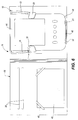
- the attachment device 10 of the present invention is shown incorporated into a folio 28 or similar device.
- the attachment device 10 is generally interconnected to a surface of the folio 28. This interconnection may be accomplished by securing the attachment device 10 to the surface of the folio by a hook and loop closure, adhesive or, in an embodiment of the attachment device 10 with an attachment aperture 26, with other variations of the attachment means identified above.
- the attachment device 10 may be secured within a layer 30, e.g. a fabric, of the folio surface.
- the attachment device 10 maybe inserted, base end 16 first, into a first opening 32, until the base 22, or base tabs 24, extend through a second opening 34.
- the layer 30 maybe secured to the surface of the folio 28, over the back surface 12 of the attachment device 10, after attachment device 10 is positioned on the surface of folio 28.
- the layer 30 may be secured by stitching, adhesive or other known assembly process.
- the folio 28 of Fig. 5 may include other features to accommodate a typical user of a PDA.
- the folio 28 of Fig. 5 shows a folio cover 36 which is hingedly interconnected to the folio 28. The folio cover 36 may then be closed on the PDA for protection during transportation of the folio 28 or storage in an attache.
- the folio cover 36 may include additional pockets 38 which maybe used, for example, to store business cards.
- the folio cover may include a webbing 40 for interconnecting a paper tablet 42 or book of Post-It Notes ®.
- the webbing 40 may be used in conjunction with a pocket 38 such that the backing of the tablet 42 may be first inserted into the pocket 38 and then the corners of the spine of the tablet 42 can be inserted into the webbing 40 to retain the tablet 42.
- a loop of material may be sewn, adhered, or otherwise interconnected to an edge of the folio 28, or at the hinge 44 of the folio to receive a pen or other writing instrument, or a stylus to be used with the PDA.
- Fig. 6 the folio 28 of Fig. 5 is shown with a PDA 44 inserted into the attachment device 10.
- the PDA base 46 is inserted into the attachment device 10 at the head end of the device 10 until the PDA base 46 contacts the base tabs 24.
- the securement arms 18 deflect outwardly to receive the PDA 44. Once the PDA 44 is properly received into attachment device 10, the securement arms 18 constrain the PDA 44 by the force created in the securement arms 18 by the deflection.
- the inward angle « of the securement arms 18 relative to the back surface 12 may be selected to provide the proper force necessary to retain the PDA 44, and may be designed specifically for various sizes and geometrical configurations of the PDA 44.
- the material of construction of the attachment device 10 may be selected to improve the resiliency of the securement arms 18.
- the securement tabs 20 as shown rest upon the forward surface of the PDA 44 and prevent movement of the PDA in this direction.
- the base tabs 24 in the embodiment of Fig. 6 are set apart. If the position of the base tabs 24 are properly selected, a communication or battery port 48 may be accessed without removing the PDA 44 from the attachment device 10.
- Fig. 7 generally depicts the embodiment shown in Fig. 1, and further identifying the fold lines showing where the securement arms 18 are interconnected to the base 22 and the securement tabs 20 interconnected to the securement arms 18.
- a substantially rigid securement arm 52 is provided on the left side portion of the back surface 12, which is in opposing relationship to a resiliently deflectable securement arm 18 positioned on the right side of the back surface 12.
- At least one base tab 24 is interconnected to a base end 16 of the back surface 12, along with an additional deflectable securement arm 18 positioned on a lower right edge of the base 12.
- the lower deflectable securement arm 18 may be removed altogether.
- a PDA 44 is removably interconnected to the PDA attachment mechanism by deflecting the securement arm 18 outwardly and positioning the PDA 44 between the rigid securement arm 52, lower base tabs 24 and deflectable securement arm 18 by applying outward pressure on the securement tab 20 positioned on the deflectable securement arm 18.
- the deflectable securement arm 18 and associated tab 20 provide a biasing force inwardly against the PDA 44 for securement until removal, at which time the securement tab 20 is again pushed outwardly to release the PDA 44 from the PDA attachment device 10.
- attachment mechanism of the present invention may be used with devices other than a PDA including, but not limited to, cellular telephones, global positioning systems (GPS), radios, and pagers.
Applications Claiming Priority (2)
| Application Number | Priority Date | Filing Date | Title |
|---|---|---|---|
| US930726 | 2001-08-15 | ||
| US09/930,726 US6520466B1 (en) | 2001-08-15 | 2001-08-15 | Personal digital assistant (PDA) attachment mechanism |
Publications (2)
| Publication Number | Publication Date |
|---|---|
| EP1284448A2 true EP1284448A2 (en) | 2003-02-19 |
| EP1284448A3 EP1284448A3 (en) | 2004-01-07 |
Family
ID=25459668
Family Applications (1)
| Application Number | Title | Priority Date | Filing Date |
|---|---|---|---|
| EP02018371A Withdrawn EP1284448A3 (en) | 2001-08-15 | 2002-08-14 | Personal digital assistant (pda) attachment mechanism |
Country Status (4)
| Country | Link |
|---|---|
| US (1) | US6520466B1 (zh) |
| EP (1) | EP1284448A3 (zh) |
| JP (1) | JP2003177840A (zh) |
| CN (1) | CN1405649A (zh) |
Cited By (2)
| Publication number | Priority date | Publication date | Assignee | Title |
|---|---|---|---|---|
| EP2420154A3 (en) * | 2010-08-20 | 2012-03-21 | Cyber Acoustics, LLC | Portable electronic Device Protector |
| US10363985B2 (en) | 2016-03-15 | 2019-07-30 | Abus August Bremicker Sohne Kg | Holder |
Families Citing this family (22)
| Publication number | Priority date | Publication date | Assignee | Title |
|---|---|---|---|---|
| US20030139149A1 (en) * | 2002-01-23 | 2003-07-24 | Grace Kao | Joint apparatus for personal digital assistant (PDA) and multimedia module |
| US6616111B1 (en) * | 2002-08-12 | 2003-09-09 | Gabriel A. White | Hand held electronic device or game impact protector |
| US7281698B2 (en) * | 2002-08-23 | 2007-10-16 | Case Logic, Inc. | Multi-positionable notebook computer case |
| US20040075035A1 (en) * | 2002-10-21 | 2004-04-22 | Knecht Richard W. | Quick connect and release holder |
| US7359184B2 (en) * | 2002-10-31 | 2008-04-15 | Hotwire Development Llc | Notebook computer protection device |
| US6892880B2 (en) * | 2003-03-05 | 2005-05-17 | Motion Systems, Llc | PDA holding unit and holding case |
| US20050072691A1 (en) * | 2003-10-02 | 2005-04-07 | Global Sourcing Group Inc. | Holder for an electronic device |
| DE102004016558A1 (de) * | 2004-04-03 | 2005-10-27 | Harald Richter | Gerätehalter für Kleincomputer oder ähnliche Geräte |
| KR100448670B1 (ko) * | 2004-05-19 | 2004-09-14 | 주식회사 현원 | 이동통신단말기용 케이스 |
| US20060088699A1 (en) * | 2004-10-22 | 2006-04-27 | Ming-Hsiang Yeh | Structure of decoration article |
| US20060293577A1 (en) * | 2005-06-23 | 2006-12-28 | Morrison Andrew E | Glucose monitoring kit |
| US7712644B2 (en) * | 2006-01-12 | 2010-05-11 | Rafalowitz Karen L | Vehicular transponder intermediary device and system |
| US20070235370A1 (en) * | 2006-03-31 | 2007-10-11 | Anthony Reale | Protective chassis cover system and method |
| US7735644B2 (en) | 2007-06-06 | 2010-06-15 | Belkin International, Inc. | Case for electrical device and method of using same |
| JP2010016799A (ja) * | 2008-06-05 | 2010-01-21 | Brother Ind Ltd | 携帯端末用カバー |
| US7911779B1 (en) | 2009-09-30 | 2011-03-22 | L&P Property Management Company | Computer docking station |
| USD667351S1 (en) * | 2011-01-07 | 2012-09-18 | Christopher Townsend | Holder for a trailer hitch ball mount assembly |
| USD747318S1 (en) * | 2012-12-24 | 2016-01-12 | eMoMo Technology Co. | Lightning to 30-pin adaptor support |
| US10061354B2 (en) | 2016-10-14 | 2018-08-28 | Gamber-Johnson Llc | Docking station for electronic device |
| USD846968S1 (en) * | 2017-06-09 | 2019-04-30 | Abus August Bremicker Sohne Kg | Bicycle lock holder |
| US11576839B2 (en) * | 2018-06-19 | 2023-02-14 | Ella Kathleen Casano | Therapeutic pouch for concealing intravenous therapy equipment |
| US10976777B2 (en) | 2019-08-15 | 2021-04-13 | Gamber-Johnson Llc | Docking station |
Citations (6)
| Publication number | Priority date | Publication date | Assignee | Title |
|---|---|---|---|---|
| US4957264A (en) * | 1989-02-08 | 1990-09-18 | Nokia-Mobira Oy | Mounting base for a telephone device, such as a mobile telephone |
| US5697071A (en) * | 1996-05-02 | 1997-12-09 | Fan; Eagle | Mobile phone holder structure |
| US5825874A (en) * | 1996-08-09 | 1998-10-20 | Nokia Mobile Phones Limited | Mobile telephone holder |
| FR2782400A1 (fr) * | 1998-08-03 | 2000-02-18 | Source Dev | Ordinateur a ecran plat |
| WO2000063834A2 (en) * | 1999-04-19 | 2000-10-26 | Ecrio, Inc. | Apparatus and method for handwriting capture |
| US6149043A (en) * | 1997-08-27 | 2000-11-21 | Nec Corporation | Holder for electronic device |
Family Cites Families (16)
| Publication number | Priority date | Publication date | Assignee | Title |
|---|---|---|---|---|
| US4406928A (en) * | 1981-04-02 | 1983-09-27 | International Telephone And Telegraph Corporation | Multi-purpose telephone holder apparatus |
| US4998277A (en) * | 1989-01-26 | 1991-03-05 | Rioux Jr Robert A | Telephone hanger for hospital bed |
| US5295649A (en) * | 1992-07-07 | 1994-03-22 | Robert Lee | Telephone support for a one-piece telephone |
| CA2194450A1 (en) | 1994-07-06 | 1996-01-18 | Truckin' Movers Corporation | Convertible carrying case and work platform |
| US5762250A (en) | 1994-07-06 | 1998-06-09 | Truckin' Movers Corporation | Convertible carrying case and work platform for small electronic devices |
| JPH08307449A (ja) * | 1995-05-10 | 1996-11-22 | Fujitsu Ltd | ファクシミリメールシステム |
| EP0783992A1 (fr) * | 1996-01-10 | 1997-07-16 | Koninklijke Philips Electronics N.V. | Dispositif de berceau pour un terminal de radio portable |
| US5899421A (en) | 1996-03-15 | 1999-05-04 | Fujitsu Limited | Stand for a portable computer |
| US5745565A (en) | 1996-05-06 | 1998-04-28 | Ericsson Inc. | Combination cup and cellular phone holder |
| US6062518A (en) * | 1997-05-20 | 2000-05-16 | United Global Sourcing Incorporated | Cellular phone retainer utilizing a cup holder |
| US5996956A (en) | 1997-06-17 | 1999-12-07 | Shawver; Michael | Mounting platform for an electronic device |
| US5898975A (en) * | 1998-01-21 | 1999-05-04 | Hancock; Dennis | Multi-purpose holder |
| US6126129A (en) * | 1998-12-18 | 2000-10-03 | Herron; Terry | Apparatus and method for supporting an intravenous solution containment vessel |
| USD426549S (en) | 1999-10-12 | 2000-06-13 | Mitsubishi Electric Information Technology Center America, Inc. (ITA.) | Slide-on accessory for a personal digital assistant |
| USD427602S (en) | 1999-10-12 | 2000-07-04 | Mitsubishi Electric Informaton Technology Center America, Inc (ITA) | Clip-on accessory for a personal digital assistant |
| USD431250S (en) | 1999-11-22 | 2000-09-26 | Herbert Richter | Palm pilot holder |
-
2001
- 2001-08-15 US US09/930,726 patent/US6520466B1/en not_active Expired - Fee Related
-
2002
- 2002-08-12 CN CN02128684A patent/CN1405649A/zh active Pending
- 2002-08-14 EP EP02018371A patent/EP1284448A3/en not_active Withdrawn
- 2002-08-15 JP JP2002237059A patent/JP2003177840A/ja active Pending
Patent Citations (6)
| Publication number | Priority date | Publication date | Assignee | Title |
|---|---|---|---|---|
| US4957264A (en) * | 1989-02-08 | 1990-09-18 | Nokia-Mobira Oy | Mounting base for a telephone device, such as a mobile telephone |
| US5697071A (en) * | 1996-05-02 | 1997-12-09 | Fan; Eagle | Mobile phone holder structure |
| US5825874A (en) * | 1996-08-09 | 1998-10-20 | Nokia Mobile Phones Limited | Mobile telephone holder |
| US6149043A (en) * | 1997-08-27 | 2000-11-21 | Nec Corporation | Holder for electronic device |
| FR2782400A1 (fr) * | 1998-08-03 | 2000-02-18 | Source Dev | Ordinateur a ecran plat |
| WO2000063834A2 (en) * | 1999-04-19 | 2000-10-26 | Ecrio, Inc. | Apparatus and method for handwriting capture |
Cited By (2)
| Publication number | Priority date | Publication date | Assignee | Title |
|---|---|---|---|---|
| EP2420154A3 (en) * | 2010-08-20 | 2012-03-21 | Cyber Acoustics, LLC | Portable electronic Device Protector |
| US10363985B2 (en) | 2016-03-15 | 2019-07-30 | Abus August Bremicker Sohne Kg | Holder |
Also Published As
| Publication number | Publication date |
|---|---|
| CN1405649A (zh) | 2003-03-26 |
| US6520466B1 (en) | 2003-02-18 |
| EP1284448A3 (en) | 2004-01-07 |
| JP2003177840A (ja) | 2003-06-27 |
Similar Documents
| Publication | Publication Date | Title |
|---|---|---|
| US6520466B1 (en) | Personal digital assistant (PDA) attachment mechanism | |
| US6264029B1 (en) | Portable organizer | |
| US8833554B2 (en) | Holding and supporting apparatus | |
| US20070057004A1 (en) | Card carrying apparatus with cell phone cradle attachment | |
| US6772879B1 (en) | Standing case for personal digital assistant | |
| US9110630B2 (en) | Portable electronic device case with an adhesive panel | |
| US20100294683A1 (en) | PLATFORM JACKET FOR AN eREADER | |
| US6266240B1 (en) | Encasement for a handheld computer | |
| US5348347A (en) | Portable phone organizer | |
| US20070262112A1 (en) | Cell phone fastening device | |
| US20050072691A1 (en) | Holder for an electronic device | |
| US20060243679A1 (en) | Computer monitor organizer | |
| US20070090007A1 (en) | Laptop Pockets | |
| US7464975B1 (en) | Apparatus for holding and transporting multiple books | |
| US5881934A (en) | Carrying box for a portable computer | |
| US20100149739A1 (en) | PROTECTIVE COVER FOR AN eREADER | |
| US7077596B1 (en) | Notebook with two-way pocket | |
| US6662733B1 (en) | Multi-leaf organizer | |
| WO2006036448A2 (en) | Foldable organizer device | |
| US20050152621A1 (en) | Computer mounted file folder apparatus | |
| US20200101885A1 (en) | Accessories for a clipboard | |
| CN207821300U (zh) | 电子装置保护套 | |
| JP2003250618A (ja) | ビジネスツール収納バッグ | |
| CA2391573C (en) | Notebook with two-way pocket | |
| JP3031468U (ja) | 携帯電話収納ホルダーを一体化したビジネス手帳ケース |
Legal Events
| Date | Code | Title | Description |
|---|---|---|---|
| PUAI | Public reference made under article 153(3) epc to a published international application that has entered the european phase |
Free format text: ORIGINAL CODE: 0009012 |
|
| AK | Designated contracting states |
Designated state(s): AT BE BG CH CY CZ DE DK EE ES FI FR GB GR IE IT LI LU MC NL PT SE SK TR |
|
| AX | Request for extension of the european patent |
Extension state: AL LT LV MK RO SI |
|
| PUAL | Search report despatched |
Free format text: ORIGINAL CODE: 0009013 |
|
| AK | Designated contracting states |
Kind code of ref document: A3 Designated state(s): AT BE BG CH CY CZ DE DK EE ES FI FR GB GR IE IT LI LU MC NL PT SE SK TR |
|
| AX | Request for extension of the european patent |
Extension state: AL LT LV MK RO SI |
|
| 17P | Request for examination filed |
Effective date: 20040705 |
|
| AKX | Designation fees paid |
Designated state(s): AT BE BG CH CY CZ DE DK EE ES FI FR GB GR IE IT LI LU MC NL PT SE SK TR |
|
| 17Q | First examination report despatched |
Effective date: 20040820 |
|
| STAA | Information on the status of an ep patent application or granted ep patent |
Free format text: STATUS: THE APPLICATION IS DEEMED TO BE WITHDRAWN |
|
| 18D | Application deemed to be withdrawn |
Effective date: 20050103 |
|
| REG | Reference to a national code |
Ref country code: HK Ref legal event code: WD Ref document number: 1053524 Country of ref document: HK |